![]()
Refer to the unit's technical manual for Cat. 2 pin availability.
Supported platforms: CODESYS 3.5, CODESYS 3.5 SAFETY
This section describes how to read and validate voltage or current sensor with AI.
This example covers two separate cases:
Validate AI value using two AI pins (two sensors)
Validate Cat. 2 safety sensor's mA signal
When using two AI pins, validation is done using the same principle for voltage and current signals.
The only difference is that AI current inputs have over current protection (see also How to read single channel sensor).
When a pin is configured as Cat. 2 mA input, two measurement AI channels are generated for one AI pin.
|
|
Refer to the unit's technical manual for Cat. 2 pin availability. |
|
|
For more information about AI pin pairs when using two AI pins for validation, refer to the safety control unit's technical manual. |
|
|
This example uses the following libraries: SafeConversion library SafeSensorCalibration library
SafeDataValidation library
SafeSSeriesHardware library
|
|
|
S_ADCToVoltageOrCurrent and S_AIOverCurrentProtection POUs are included in the code template generated by MultiTool Creator.
|
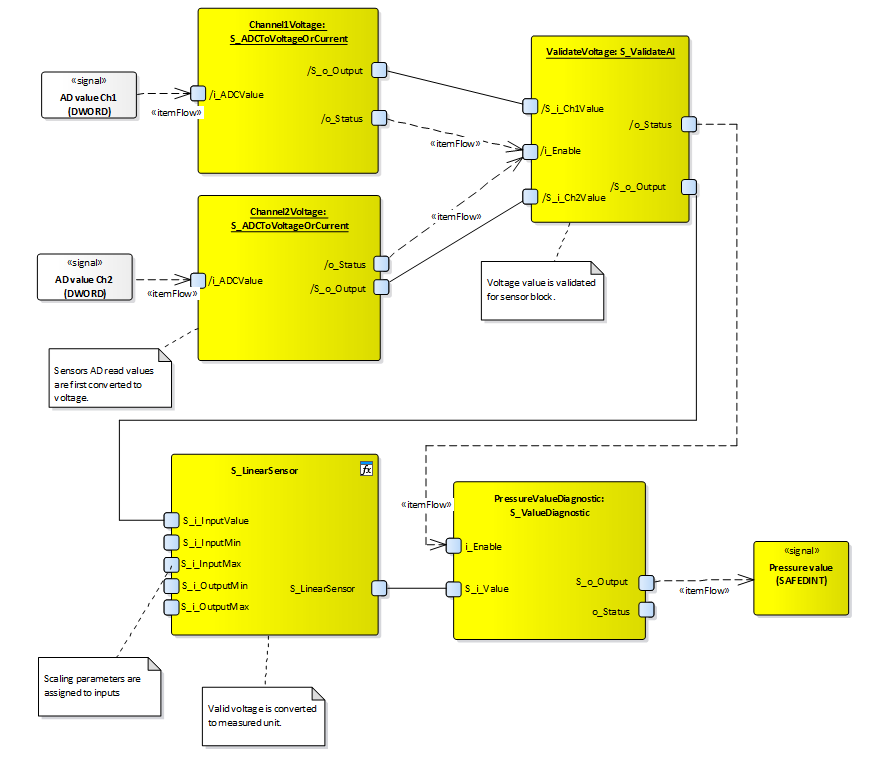
The architecture example below refers to voltage values, but principle are the same for all input types (AI voltage, AI current, Cat. 2).
When AI is configured in mA mode or Cat. 2, over current monitoring is added, which is not present in the image below (see also How to read single channel sensor).
|
|
When the following example is used with non-safety I/O, the I/O variables are generated in Inputs program instead of S_Inputs. |
This example's principle applies to:
Using two AI pins in mA mode (use also AiOverCurrentStatus as a validation enable condition)
Using two AI pins in voltage mode
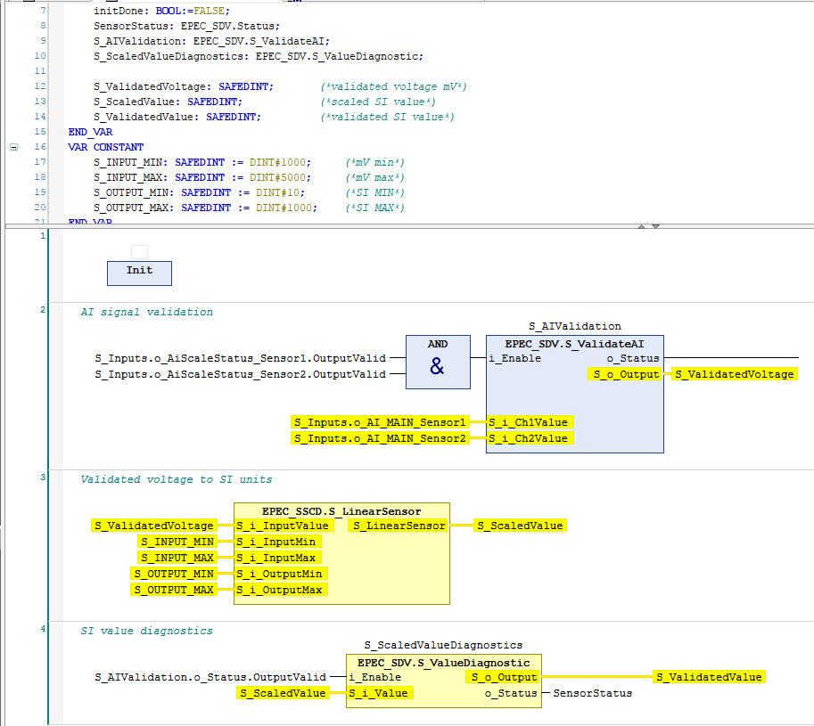
The following example, demonstrates the reading and validating of two AI sensor values ("Sensor1" and "Sensor2" AI pins defined in MultiTool Creator).
Sensor1 is the main channel in the following example (channel1 in validation).
The following example code is for voltage input.
|
Code at Safe PRG:
|
|
|
|
|
|
Init method: |
|
IF NOT initDone THEN initDone := TRUE; (*application specific validation parameters*) S_AIValidation.Init( S_i_InvertedCh2 := FALSE, S_i_DiagnosticDelay := EPEC_HW.Constants.G_VOLTAGE_INPUT_DIAGNOSTIC_DELAY, S_i_SafeOutputValue := EPEC_HW.Constants.G_VOLTAGE_INPUT_SAFE_VALUE, S_i_Tolerance := DINT#100, S_i_SumValue := DINT#0, i_pEventCode := ADR(S_Inputs.o_EventCode_Sensor1), i_pEventCodeCh2 := ADR(S_Inputs.o_EventCode_Sensor2) ); (*application specific diagnostic limits*) S_ScaledValueDiagnostics.Init( S_i_HighErrorLimit := DINT#800, S_i_LowErrorLimit := DINT#10, S_i_EnableHighError := TRUE, S_i_EnableLowError := TRUE, S_i_DiagnosticDelay := UINT#20, S_i_SafeOutputValue := DINT#0, i_pEventCode := ADR(S_Inputs.o_EventCode_Sensor1) ); END_IF |
|
|
|
Init method: |
|
IF NOT initDone THEN initDone := TRUE; (*application specific validation parameters*) S_AIValidation.Init( S_i_InvertedCh2 := FALSE, S_i_DiagnosticDelay := EPEC_HW.Constants.G_VOLTAGE_INPUT_DIAGNOSTIC_DELAY, S_i_SafeOutputValue := EPEC_HW.Constants.G_VOLTAGE_INPUT_SAFE_VALUE, S_i_Tolerance := DINT#30, S_i_SumValue := DINT#0, S_i_ReferenceValue := DINT#5000, // Example uses 5V as tolerance reference i_pEventCode := ADR(S_Inputs.o_EventCode_Sensor1), i_pEventCodeCh2 := ADR(S_Inputs.o_EventCode_Sensor2) ); (*application specific diagnostic limits*) S_ScaledValueDiagnostics.Init( S_i_HighErrorLimit := DINT#800, S_i_LowErrorLimit := DINT#10, S_i_EnableHighError := TRUE, S_i_EnableLowError := TRUE, S_i_DiagnosticDelay := UINT#20, S_i_SafeOutputValue := DINT#0, i_pEventCode := ADR(S_Inputs.o_EventCode_Sensor1) ); END_IF |
|
|
|
|
When the following example is used with non-safety I/O, the I/O variables are generated in Inputs program instead of S_Inputs. |
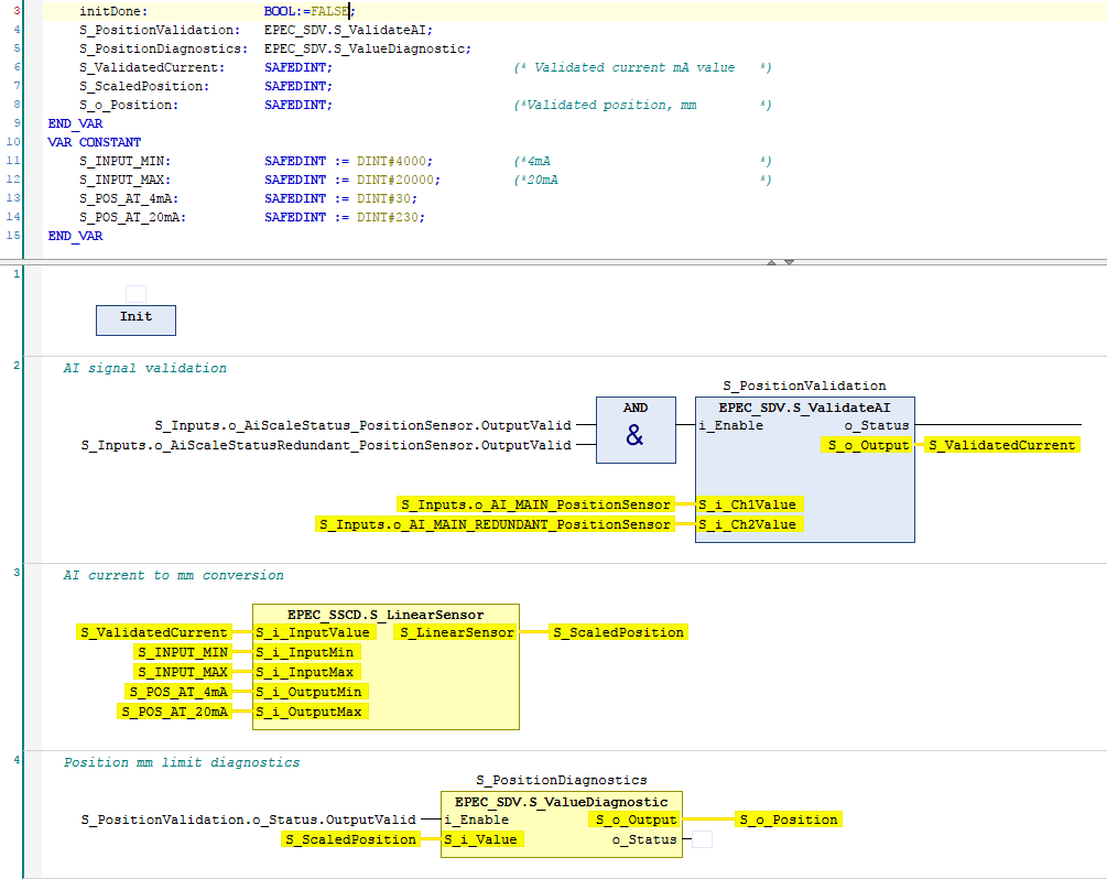
This example applies to an AI pin which is configured in Cat. 2 mode in MultiTool Creator.
The following example demonstrates the reading and validating of Cat. 2 safety mA-sensor signal (PositionSensor Cat. 2 signal defined in MultiTool Creator).
|
Code at safe PRG: |
|
|
|
Init method: |
|
IF NOT initDone THEN initDone := TRUE; (*application specific validation parameters*) S_PositionValidation.Init( S_i_InvertedCh2 := FALSE, S_i_DiagnosticDelay := EPEC_HW.Constants.G_CURRENT_INPUT_DIAGNOSTIC_DELAY, S_i_SafeOutputValue := EPEC_HW.Constants.G_CURRENT_INPUT_SAFE_VALUE, S_i_Tolerance := DINT#100, S_i_SumValue := DINT#0, i_pEventCode := ADR(S_Inputs.o_EventCode_PositionSensor), i_pEventCodeCh2 := ADR(S_Inputs.o_EventCode_PositionSensor) ); (*application specific diagnostic limits*) S_PositionDiagnostics.Init( S_i_HighErrorLimit := DINT#200, S_i_LowErrorLimit := DINT#50, S_i_EnableHighError := TRUE, S_i_EnableLowError := TRUE, S_i_DiagnosticDelay := UINT#50, S_i_SafeOutputValue := DINT#0, i_pEventCode := ADR(S_Inputs.o_EventCode_PositionSensor) ); END_IF |
|
Init method: |
|
IF NOT initDone THEN initDone := TRUE; (*application specific validation parameters*) S_PositionValidation.Init( S_i_InvertedCh2 := FALSE, S_i_DiagnosticDelay := EPEC_HW.Constants.G_CURRENT_INPUT_DIAGNOSTIC_DELAY, S_i_SafeOutputValue := EPEC_HW.Constants.G_CURRENT_INPUT_SAFE_VALUE, S_i_Tolerance := DINT#20, S_i_SumValue := DINT#0, S_i_ReferenceValue := DINT#20000, // Example uses 20mA as tolerance reference i_pEventCode := ADR(S_Inputs.o_EventCode_PositionSensor), i_pEventCodeCh2 := ADR(S_Inputs.o_EventCode_PositionSensor) ); (*application specific diagnostic limits*) S_PositionDiagnostics.Init( S_i_HighErrorLimit := DINT#200, S_i_LowErrorLimit := DINT#50, S_i_EnableHighError := TRUE, S_i_EnableLowError := TRUE, S_i_DiagnosticDelay := UINT#50, S_i_SafeOutputValue := DINT#0, i_pEventCode := ADR(S_Inputs.o_EventCode_PositionSensor) ); END_IF |
S_ValidateAI (FB)
S_LinearSensor (FUN)
S_ValueDiagnostic (FB)
Source file topic100546.htm
Last updated 4-Sep-2025