![]()
This function block can validate any numeric value (quantity), not only voltage, current or resistance.
Supported platforms: CODESYS 3.5, CODESYS 3.5 SAFETY, CODESYS 3.5 SP19 SAFETY
This function block validates an analog value by comparing two analog signals. The signals must be of same type and scaling.
Values can be any numeric value. The channel 2 value can be inverted.
|
|
This function block can validate any numeric value (quantity), not only voltage, current or resistance. |
Init method is used to initialize the necessary static calculation parameters for the function block instance.
The method shall be called at least once before the actual function block can be called, i.e. at the application initialization phase.
The method checks the validity of input parameters. However, none of the function block outputs are affected by the initialization.
|
|
A parameter error is diagnosed if: • Init method is not called before the main FB call OR • i_pEventCode = 0 OR • i_pEventCodeCh2 = 0 OR • S_i_Tolerance is out of range
|
|
Parameter |
Data type |
Unit |
Range |
Description |
|
S_i_InvertedCh2 |
SAFEBOOL |
- |
- |
Input channel 2 is inverted. |
|
S_i_SafeOutputValue |
SAFEDINT |
- |
- |
Safe output value in case of error. |
|
S_i_DiagnosticDelay |
SAFEUINT |
ms |
- |
Delay time for diagnostics. |
|
S_i_Tolerance |
SAFEDINT |
‰ |
0 – 1000 |
Tolerance for error diagnostics. |
|
S_i_SumValue |
SAFEDINT |
same as channel value’s |
|
Sum value of channels, used when channel 2 is inverted. |
|
i_pEventCode |
POINTER TO EventCode |
- |
≠0 |
Pointer to application variable which is type EventCode. Used with POUs that handle signal data. |
|
i_pEventCodeCh2 |
POINTER TO EventCode |
- |
≠0 |
Pointer to application variable which is type EventCode. Used with POUs that handle validation signal data. |
|
Parameter |
Data type |
Unit |
Range |
Description |
|
S_i_InvertedCh2 |
SAFEBOOL |
- |
- |
Input channel 2 is inverted. |
|
S_i_SafeOutputValue |
SAFEDINT |
- |
- |
Safe output value in case of error. |
|
S_i_DiagnosticDelay |
SAFEUINT |
ms |
- |
Delay time for diagnostics. |
|
S_i_Tolerance |
SAFEDINT |
‰ |
0 – 1000 |
Tolerance for error diagnostics. |
|
S_i_SumValue |
SAFEDINT |
same as channel value’s |
|
Sum value of channels, used when channel 2 is inverted. |
|
S_i_ReferenceValue |
SAFEDINT |
same as channel value’s |
|
Reference value for tolerance calculation in redundant mode |
|
i_pEventCode |
POINTER TO EventCode |
- |
≠0 |
Pointer to application variable which is type EventCode. Used with POUs that handle signal data. |
|
i_pEventCodeCh2 |
POINTER TO EventCode |
- |
≠0 |
Pointer to application variable which is type EventCode. Used with POUs that handle validation signal data. |
Initialization method return value
|
TRUE: All initialization parameters ok. |
|
FALSE: Error in initialization parameter(s). |
This function block has two operation modes: Redundant and inverted.
In redundant mode the S_i_Ch1Value is directly compared to S_i_Ch2Value. The difference is calculated by subtracting the smaller value from the larger. The tolerance value is per mil of channel 1 value. If the difference value is smaller or equal to the tolerance value, and no error has occurred, the signal is considered as valid and S_i_Ch1Value is written to S_o_Output.
In inverted mode, the sum of S_i_Ch1Value and S_i_Ch2Value is compared to S_i_SumValue. If the sum values are within given tolerance and no error has occurred, the signal is considered as valid and S_i_Ch1Value is written to S_o_Output.
The block sets o_Status.OutputValid state TRUE if signals are valid and operation is enabled, i.e. i_Enable is TRUE
This function block has two operation modes: Redundant and inverted.
In redundant mode the S_i_Ch1Value is directly compared to S_i_Ch2Value. The difference is calculated by subtracting the smaller value from the larger. The tolerance value is per mil of reference value (S_i_Tolerance * S_i_ReferenceValue / 1000). If the difference value is smaller or equal to the tolerance value, and no error has occurred, the signal is considered as valid and S_i_Ch1Value is written to S_o_Output.
In inverted mode, the sum of S_i_Ch1Value and S_i_Ch2Value is compared to S_i_SumValue. If the sum values are within given tolerance and no error has occurred, the signal is considered as valid and S_i_Ch1Value is written to S_o_Output.
The block sets o_Status.OutputValid state TRUE if signals are valid and operation is enabled, i.e. i_Enable is TRUE
If channel states mismatch continuously over S_i_DiagnosticDelay time, then
• S_o_Output is set to given safe value,
• Status o_Status.OutputValid is set FALSE,
• The corresponding Error bit in o_Status variable is set TRUE, and
• The corresponding EventID is set to i_pEventCode
All FB statuses, including errors are reset on rising edge of i_Enable.
|
Input variable name |
Data type |
Range |
Description |
|
i_Enable |
BOOL |
- |
Enables validation functionality |
|
S_i_Ch1State |
SAFEDINT |
See description |
Input channel 1 (signal) value |
|
S_i_Ch2State |
SAFEDINT |
Same as channel 1 value’s |
Input channel 2 (validation) value |
|
Output variable name |
Data type |
Range |
Description |
|
S_o_Output |
SAFEDINT |
Same as channel 1 value’s |
Validated value. |
|
o_Status |
Status |
- |
Status of output value. See Status structure. |
See Diagnostic Interface library description of error status and event code functionality.
|
Conditions |
S_o_Output value |
o_Status. OutputValid |
o_Status error status |
Event code FunctionID |
Event code EventID |
|
i_Enable TRUE AND init parameter error AND i_pEventCode valid |
S_i_Safe OutputValue |
FALSE |
ParameterError |
VALIDATE_AI |
PARAMETER_ERROR |
|
i_Enable TRUE AND init parameter error AND |
S_i_Safe OutputValue |
FALSE |
ParameterError |
- |
- |
|
i_Enable rises AND init parameters ok AND inputs match |
S_i_Ch1Value |
TRUE |
- |
NO_FUNC |
NO_ERROR |
|
i_Enable TRUE AND init parameters ok AND inputs mismatch |
S_i_Safe OutputValue |
FALSE |
ValueMismatch |
VALIDATE_AI |
DATA_MISMATCH |
|
|
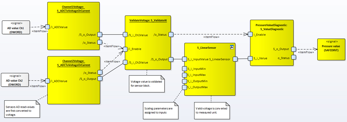
Validation code is NOT generated by MultiTool Creator. The S_ADCToVoltageOrCurrent POUs are included in code template. |
|
|
See examples from How-To Guides (links below) |
|
|
When using same type of sensors (equal resistance, current etc.): Validation can be done before sensor function block. |
|
|
For more diversity, different sensors can also be used. For example, using PT and KTY, validation must be done using temperature values. |
Source file topic100386.htm
Last updated 4-Sep-2025