Supported platforms: CODESYS 3.5, CODESYS 3.5 SAFETY, CODESYS 3.5 SP19 SAFETY
S_ADCToVoltageOrCurrent (FB)
Description
This function block is used to convert control unit AD converter value to current (µA) or voltage (mV). The function block can be used when analog sensors (0-5V, 0-10V or 0-22mA) are connected to control unit’s AI pin. Cat. 2 type AI pin is also supported.
Initialization
Init method is used to initialize the necessary static calculation parameters for the function block instance.
The method shall be called at least once before the actual function block can be called, i.e. at the application initialization phase.
The method checks the validity of input parameters. However, none of the function block outputs are affected by the initialization.
|

|
A parameter error is diagnosed if:
-
Init method is not called before the main FB call OR
-
i_pEventCode = 0 OR
-
S_i_OutputMaximum <= 0 OR
-
S_i_OutputHighLimit > S_i_OutputMaximum OR
-
S_i_OutputLowLimit >= S_i_OutputHighLimit OR
-
S_i_OutputLowLimit < 0
|
|
|
S_i_Cat2MonitoringCh is set to TRUE only to current input pin's redundant-channel.
|
Initialization parameters
|
Parameter
|
Type
|
Unit
|
Range
|
Description
|
|
S_i_OutputMaximum
|
ENUM
|
mV /µA
|
EPEC_HW. VALUE_AT_ AD_MAXIMUM
|
mV/µA value at AD maximum
|
|
S_i_OutputHighLimit
|
SAFEDINT
|
mV / µA
|
>0
|
Limit value for status o_Status.OutputTooHigh
|
|
S_i_OutputLowLimit
|
SAFEDINT
|
mV /µA
|
>=0
|
Limit value for status o_Status.OutputTooLow
|
|
S_i_DiagnosticDelay
|
SAFEUINT
|
ms
|
-
|
Delay time for output high/low diagnostics
|
|
S_i_Cat2MonitoringCh
|
SAFEBOOL
|
-
|
-
|
Is this channel a CAT2 monitoring channel.
|
|
i_pEventCode
|
POINTER TO EventCode
|
-
|
≠0
|
Pointer to application variable which is type EventCode.
|
Initialization method return value
|
TRUE: All initialization parameters ok.
|
|
FALSE: Error in initialization parameter(s).
|
Operation
When i_Enable is TRUE, the function block converts the input ADC value (i_ADCValue) to voltage (mV) or current (µA) value.
The input pin type can be either voltage or current.
If Cat. 2 monitoring channel is not in use the equation 3 can be used to calculate output value.
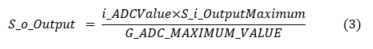
S_o_Output minimum is however limited to 0.
If Cat. 2 monitoring channel is in use then output current can be calculated with equation 4
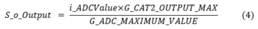
, where G_CAT2_OUTPUT_MAX is theoretical maximum current.
If the calculated output value is lower than S_i_OutputLowLimit or higher than S_i_OutputHighLimit for longer (≥) than given diagnostic delay time, the corresponding error output is set.
A parameter error is diagnosed if AD input value exceeds defined maximum value G_ADC_MAXIMUM_VALUE.
The output S_o_Output is set to safe value (0) if any error occurs, also o_Status.OutputValid is set false and the corresponding event ID is set to EventCode.
Limitations
|

|
Cat. 2 monitoring channel can be used only with current input pin.
|
Inputs
|
Input variable name
|
Data type
|
Range
|
Description
|
|
i_Enable
|
BOOL
|
TRUE / FALSE
|
Enable calculation
|
|
i_ADCValue
|
DWORD
|
0 - G_ADC_MAXIMUM_VALUE
|
AD converter value to be scaled
|
Outputs
|
Output variable name
|
Data type
|
Unit
|
Range
|
Description
|
|
S_o_Output
|
SAFEDINT
|
mV / µA
|
-
|
Calculated voltage or current value
|
|
o_Status
|
Status
|
-
|
-
|
Status of output value. See Status structure.
|
Error diagnostic
See Diagnostic Interface library description of error status and event code functionality.
|
Conditions
|
S_o_Output value
|
o_Status. OutputValid
|
o_Status error status
|
Event code FunctionID
|
Event code EventID
|
|
i_Enable TRUE
AND
init parameter error AND
i_pEventCode valid
|
0
|
FALSE
|
ParameterError
|
ADC_TO_VOLTAGE OR_CURRENT
|
PARAMETER_ERROR
|
|
i_Enable TRUE
AND
init parameter error AND
i_pEventCode NULL
|
0
|
FALSE
|
ParameterError
|
-
|
-
|
|
i_Enable rises
AND
init parameters ok AND
S_i_OutputLowLimit <= S_o_Output <= S_i_OutputHighLimit
|
calculated value
|
TRUE
|
-
|
NO_FUNC
|
NO_ERROR
|
|
i_Enable TRUE
AND
parameters ok
AND
S_o_Output > S_i_OutputHighLimit
|
0
|
FALSE
|
OutputHigh
|
ADC_TO_VOLTAGE OR_CURRENT
|
OUTPUT_TOO_HIGH
|
|
i_Enable TRUE
AND
parameters ok
AND
S_o_Output < S_i_OutputLowLimit
|
0
|
FALSE
|
OutputLow
|
ADC_TO_VOLTAGE OR_CURRENT
|
OUTPUT_TOO_LOW
|
Example code
|
|
MultiTool Creator generated code includes this function block, when the input is selected to use.
|
|
|
Location of the POU instance depends on the application: Non-safe inputs are handled in non-safe context, safe inputs are handled in safe context. The example code applies to both.
|
|
Definitions:
|
|
|
(*NOTE! This object is created by Epec MultiTool Creator*)
VAR_INPUT
i_Enable: BOOL := TRUE;
i_AI_XM1_3:DWORD; // Input AD value
END_VAR
VAR_OUTPUT
S_o_AI_XM1_3: SAFEDINT; // Non-validated voltage value (mV)
o_XM1_3_Status_ToVoltage: EPEC_SC.Status; // Conversion status
o_XM1_3_EventCode: EPEC_DITF.EventCode; // Event code of the input
END_VAR
VAR
S_1_03_ToVoltage: EPEC_SC.S_ADCToVoltageOrCurrent;
init_ok: BOOL := FALSE;
END_VAR
|
|
|
|
Initialization:
|
|
|
(*NOTE! This object is created by Epec MultiTool Creator*)
o_XM1_3_EventCode.DeviceID := DeviceIDs.VoltageInput;
o_XM1_3_EventCode.ChannelID := ChannelIDs.Ch1;
o_XM1_3_EventCode.FunctionID := EPEC_DITF.FunctionIDs.NO_FUNC; // No function has detected an error
o_XM1_3_EventCode.EventID := EPEC_DITF.ErrorIDs.NO_ERROR; // No error occurred by default
init_ok := S_1_03_ToVoltage.Init(
S_i_OutputMaximum := EPEC_HW.VALUE_AT_AD_MAXIMUM.U_TYPE096_5V, // 5V input
S_i_OutputHighLimit := EPEC_HW.Constants.G_AI_5V_HIGH_VOLTAGE, // High limit of voltage value
S_i_OutputLowLimit := EPEC_HW.Constants.G_AI_LOW_VOLTAGE, // Low limit of voltage value
S_i_Cat2MonitoringCh:= FALSE, // Input is not a CAT2 monitoring channel
S_i_DiagnosticDelay := EPEC_HW.Constants.G_VOLTAGE_INPUT_DIAGNOSTIC_DELAY, // Delay for error diagnostic
i_pEventCode := ADR(o_EC_XM1_3) // Event code pointer for FB
);
|
|
Code:
|
|
|
(*NOTE! This object is created by Epec MultiTool Creator*)
S_1_03_ToVoltage(
i_Enable := i_Enable,
i_ADCValue := i_AI_XM1_3,
o_Status => o_XM1_3_Status_ToVoltage,
S_o_Output => S_o_AI_XM1_3
);
|
|
|
See also