Description
This function block can be used to convert voltage (mV) to DI status value (TRUE/FALSE) for example when button or relay is connected to control unit’s AI pin.
Initialization
Init method is used to initialize the necessary static calculation parameters for the function block instance.
The method shall be called at least once before the actual function block can be called, i.e. at the application initialization phase.
The method checks the validity of input parameters. However, none of the function block outputs are affected by the initialization.
|
|
A parameter error is diagnosed if:
|
Initialization parameters
|
Parameter |
Type |
Unit |
Range |
Description |
|
S_i_ThresholdHigh |
SAFEDINT |
mV |
>0 |
Threshold voltage value to set output TRUE |
|
S_i_ThresholdLow |
SAFEDINT |
mV |
>0 |
Threshold voltage value to set output FALSE |
|
i_pEventCode |
POINTER TO EventCode |
- |
≠0 |
Pointer to application variable which is type EventCode. |
Initialization method return value
|
TRUE: All initialization parameters ok. |
|
FALSE: Error in initialization parameter(s). |
Operation
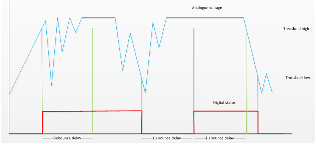
This function block is in the normal operation mode when the input i_Enable is TRUE and all input parameters are valid. In normal operation mode the function block converts voltage (mV) to digital status (true/false). The output status is set to true when the input voltage exceeds the given high threshold voltage value, and it is set to false when the input voltage falls below the given low threshold voltage value.
Inputs
|
Input variable name |
Data type |
Range |
Description |
|
i_Enable |
BOOL |
TRUE / FALSE |
Enable conversion |
|
S_i_Voltage |
mV |
>=0 |
AI pin voltage |
Outputs
|
Output variable name |
Data type |
Range |
Description |
|
S_o_DigitalState |
SAFEBOOL |
TRUE / FALSE |
De-bounced DI status |
|
o_Status |
Status |
- |
Status of output value. See Status structure. |
Error diagnostic
See Diagnostic Interface library description of error status and event code functionality.
|
Conditions |
S_o_Digital State |
o_Status. OutputValid |
o_Status error status |
Event code FunctionID |
Event code EventID |
|
i_Enable TRUE AND init parameter error AND i_pEventCode valid |
FALSE |
FALSE |
ParameterError |
VOLTAGE_TO_DI |
PARAMETER_ERROR |
|
i_Enable TRUE AND init parameter error AND |
FALSE |
FALSE |
ParameterError |
- |
- |
|
i_Enable rises AND init parameters ok |
de-bounced DI status |
TRUE |
- |
NO_FUNC |
NO_ERROR |
|
i_Enable TRUE AND S_i_Voltage < 0 * |
FALSE |
FALSE |
ParameterError |
VOLTAGE_TO_DI |
PARAMETER_ERROR |
|
|
* Not an initialization parameter error. |
Example code
|
|
MultiTool Creator generated code includes this function block, when the input is selected to be a DI. |
|
|
This FB's input data is voltage. The voltage value needs to be converted from AD value with S_ADCToVoltageOrCurrent FB. |
|
|
Location of the POU instance depends on the application: Non-safe inputs are handled in non-safe context, safe inputs are handled in safe context. The example code applies to both. |
|
Definitions: |
|
|
(*NOTE! This object is created by Epec MultiTool Creator*)
VAR_INPUT i_Enable: BOOL := TRUE; i_AI_XM1_03:DWORD; // Input AD value END_VAR VAR_OUTPUT S_o_DI_XM1_03: SAFEBOOL; o_XM1_03_Status_ToVoltage: EPEC_SC.Status; o_XM1_03_Status_ToDI: EPEC_SC.Status; o_XM1_03_Status_DebounceDI: EPEC_SC.Status; o_EC_XM1_03: EPEC_DITF.EventCode; END_VAR VAR init_ok: BOOL := FALSE; S_1_03_ToVoltage: EPEC_SC.S_ADCToVoltageOrCurrent; S_1_03_VoltageToDI: EPEC_SC.S_VoltageToDI; S_1_03_DebounceDI: EPEC_SC.S_DebounceDI;
S_XM1_03_ThresholdHigh: SAFEDINT := DINT#3500; // mV S_XM1_03_ThresholdLow: SAFEDINT := DINT#2500; // mV S_XM1_03_DebounceDelay: SAFEUINT := UINT#30; // ms END_VAR
|
|
|
|
|
|
Init: |
|
|
(*NOTE! This object is created by Epec MultiTool Creator*)
o_EC_XM1_03.DeviceID := DeviceIDs.DigitalInput; o_EC_XM1_03.ChannelID := ChannelIDs.Ch1; o_EC_XM1_03.FunctionID := EPEC_DITF.FunctionIDs.NO_FUNC; o_EC_XM1_03.EventID := EPEC_DITF.ErrorIDs.NO_ERROR;
init_ok := S_1_03_ToVoltage.Init( S_i_OutputMaximum := EPEC_HW.VALUE_AT_AD_MAXIMUM.U_TYPE096_5V, // 5V input S_i_OutputHighLimit := EPEC_HW.VALUE_AT_AD_MAXIMUM.U_TYPE096_5V, // DI uses maximum measurement range S_i_OutputLowLimit := EPEC_HW.Constants.G_AI_LOW_VOLTAGE, // Low limit of voltage value S_i_Cat2MonitoringCh:= FALSE, // Input is not a CAT2 monitoring channel S_i_DiagnosticDelay := EPEC_HW.Constants.G_VOLTAGE_INPUT_DIAGNOSTIC_DELAY, // Delay for error diagnostic i_pEventCode := ADR(o_EC_XM1_03) // Event code pointer for FB );
init_ok := init_ok AND S_1_03_VoltageToDI.Init( S_i_ThresholdHigh:=S_XM1_03_ThresholdHigh, S_i_ThresholdLow:=S_XM1_03_ThresholdLow, i_pEventCode:=ADR(o_EC_XM1_03) );
init_ok := init_ok AND S_1_03_DebounceDI.Init( S_i_DebounceDelay:=S_XM1_03_DebounceDelay, i_FilterType:=EPEC_SC.DebounceFilterType.Debounce_Fast, i_pEventCode:=ADR(o_EC_XM1_03) );
|
|
|
Code: |
|
|
(*NOTE! This object is created by Epec MultiTool Creator*)
S_1_03_ToVoltage( i_Enable := i_Enable, i_ADCValue := i_AI_XM1_03, o_Status =>, S_o_Output => );
S_1_03_VoltageToDI( i_Enable := S_1_03_ToVoltage.o_Status.OutputValid, S_i_Voltage := S_1_03_ToVoltage.S_o_Output, o_Status => o_XM1_03_Status_ToDI, S_o_DigitalState => );
S_1_03_DebounceDI( i_Enable:=S_1_03_VoltageToDI.o_Status.OutputValid, S_i_DigitalState:=S_1_03_VoltageToDI.S_o_DigitalState, o_Status => o_XM1_03_Status_DebounceDI, S_o_DigitalState => S_o_DI_XM1_03 );
|
|