![]()
Hardware diagnostics have an output S_o_DiagStatusOk which indicates that all monitored safety diagnostics are OK. See control unit specific diagnostic program's manual for more information on diagnostic conditions.
Supported platforms: CODESYS 3.5, CODESYS 3.5 SAFETY
This section describes how to use hardware diagnostics in S Series / E Series Control Units.
It also describes how to control an output group and reference voltage output by an application.
The architecture of the HW diagnostic depends on used safety library versions:
In SP10 safety libraries (V1.X) hardware diagnostics are implemented by the SafeSSeriesHardware library in a control unit specific program
(e.g. S_SC52_Diagnostic (PRG)).
Program is used with the SafeSSeriesHardware library's EPEC_SHWD namespace.
In SP19 safety libraries (V2.X) hardware diagnostics are implemented by control unit specific library (e.g. SafeSL8XDiagnostic library).
HW diagnostic library contains control unit specific program (e.g. S_SL8X1_Diagnostic (PRG))
Program is used with the EPEC_HWDIAG namespace.
|
|
Hardware diagnostics have an output S_o_DiagStatusOk which indicates that all monitored safety diagnostics are OK. See control unit specific diagnostic program's manual for more information on diagnostic conditions. |
|
|
The hardware specific diagnostic program is executed in MultiTool Creator code template.
|
|
|
Control unit specific hardware diagnostic errors are also added to application log when MultiTool Creator code template is used (MT 6.4 / SDK3.6 or later). See also How to use application error log. |
Output group control and reference voltage control are activated by writing the following diagnostic program inputs.
|
|
The default state of the output group and reference voltage output controls are OFF. |
|
|
Control conditions are application specific. |
|
|
S_o_DiagStatusOk status affects MultiTool Creator code template's status G_StatusFlags_Safe.S_SafeOperationEnable
The application shall use S_SafeOperationEnable as a condition for safety related controls. |
|
|
Output group control can only be activated once. After output group deactivation, reboot is required for output group re-activation. |
|
|
Output group control is automatically deactivated if a firmware error or output group validation error is detected. |
|
|
Following control inputs are not set in code template. |
The following is an example of output group and reference voltage control
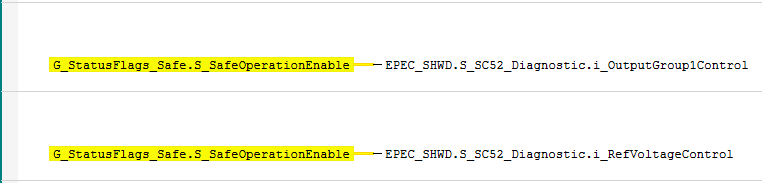
The current state of controls can be read by the application from the following variables:
EPEC_SHWD.S_SC52_Diagnostic.S_o_OutputGroup1Control
EPEC_SHWD.S_SC52_Diagnostic.S_o_RefControl
The application can also access all other output variables from the diagnostic program such as measured voltages and
status variables for each measurement.
|
|
SL84 product does not have output group control. Output group voltages are supplied externally. Supply group 1 voltage is monitored by library and affects S_o_DiagStatusOk. Supply group 2 & 3 voltages are measured but not diagnosed by library. See also S_SL84_Diagnostic (PRG) |
|
|
The default state of the reference voltage output control is OFF. |
|
|
S_o_DiagStatusOk status affects MultiTool Creator code template's status G_StatusFlags_Safe.S_SafeOperationEnable
The application shall use S_SafeOperationEnable as a condition for safety related controls. |
|
|
The code template includes status flags for monitoring each output group's voltage in G_StatusFlags_Safe global variable list. E.g. G_StatusFlags_Safe.S_OutputGroup2VoltageOK.
Status flag is TRUE when corresponding output group voltage is within low/high limits. Status flags are also reset to FALSE when S_SafeOperationEnable is FALSE. Status flags do not have delay.
These status flags should be used by application as a condition when controlling outputs in addition to S_SafeOperationEnable. Otherwise the output diagnostic blocks will trigger error if output is controlled ON when output group voltage is not supplied. |
|
|
Control conditions are application specific. |
|
|
The following control inputs are not set in the code template. |
The following is an example of reference voltage control
Code:
EPEC_SHWD.S_SL84_Diagnostic.i_RefVoltageControl := G_StatusFlags_Safe.S_SafeOperationEnable;
The current state of control can be read by the application from the following variable:
EPEC_SHWD.S_SL84_Diagnostic.S_o_RefControl
The application can also access all other output variables from the diagnostic program such as measured voltages and status variables for each measurement.
Output group control and reference voltage control are activated by writing the following diagnostic program inputs.
|
The default state of the output group and reference voltage output controls are OFF. |
|
|
Control conditions are application specific. |
|
|
S_o_DiagStatusOk status affects MultiTool Creator code template's status G_StatusFlags.SystemOk. |
|
|
Output group control is automatically deactivated if a firmware error or output group validation error is detected. |
|
|
Following control inputs are not set in code template. |
The following is an example of output group and reference voltage control
|
Code: |
|
|
IF G_StatusFlags.SystemOk THEN EPEC_SHWD.S_EC44_Diagnostic.i_OutputGroup1Control := TRUE; EPEC_SHWD.S_EC44_Diagnostic.i_RefVoltageControl := TRUE; ELSE EPEC_SHWD.S_EC44_Diagnostic.i_OutputGroup1Control := FALSE; EPEC_SHWD.S_EC44_Diagnostic.i_RefVoltageControl := FALSE; END_IF
|
|
The current state of controls can be read by the application from the following variables:
EPEC_SHWD.S_EC44_Diagnostic.S_o_OutputGroup1Control
EPEC_SHWD.S_EC44_Diagnostic.S_o_RefControl
The application can also access all other output variables from the diagnostic program such as measured voltages and status variables for each measurement.
MultiTool Creator code template uses S_SC4X1_Diagnostic (PRG) for SC4X1 unit's HW diagnostics.
See the PRG's manual for description on diagnostics and functionalities that are implemented by library.
This guide gives application examples on controls that are required to be performed by the application and also information on status indications that are provided for application controls.
Code template
|
|
S_o_DiagStatusOk affects MultiTool Creator code template's status G_StatusFlags_Safe.S_SafeOperationEnable
S_SafeOperationEnable is set FALSE if diagnostic error is detected in a functionalities which affect the S_o_DiagStatusOk. The application shall use S_SafeOperationEnable as a condition for safety related controls. |
When code template is generated by MultiTool Creator, the S_Main PRG contains example on application controls for the HW diagnostic inputs.
Safety switch startup test
Safety switch startup test is triggered by application. This allows the application to delay the startup test execution, if necessary.
Delaying the startup test can be required in system condition where the supply voltage fluctuates after system bootup.
|
The startup test will perform tests for the safety switch and also check for external voltages in outputs. See product's safety manual for more information. |
|
If application wants to avoid FW error during startup test due to the output's external voltage, the application can diagnose the outputs before triggering the startup test. See How to control DO & DO ECO for information on how to diagnose the output with DOS status. |
Startup test is started by setting following input TRUE:
|
Code: |
|
EPEC_HWDIAG.S_SC4X1_Diagnostic.i_SwitchStartupTestEnable := TRUE; |
Output group control
|
|
The default state of the output group control is OFF. Control conditions are application specific. |
|
|
Output group control can only be activated once. After output group deactivation, reboot is required for output group re-activation. |
|
|
Output group control is automatically deactivated in following conditions:
|
|
After the startup test has been executed and output group is activated, the external voltage diagnostic in output pins is application's responsibility. See How to control DO & DO ECO for information on how to diagnose the outputs with DOS status. |
Startup test execution is required before output group can be controlled. The code template's S_SafeOperationEnable status is not TRUE before output group diagnostic is enabled in library.
The output group diagnostic's enable status can also be read from following variable:
EPEC_HWDIAG.S_SC4X1_Diagnostic.o_DiagEnableStates.OutputGroup1_Diagnostic_Enable
The following is an example of output group control
|
Code: |
|
EPEC_HWDIAG.S_SC4X1_Diagnostic.i_OutputGroup1Control := G_StatusFlags_Safe.S_SafeOperationEnable; |
The current state of control can be read by the application from the following variable:
EPEC_HWDIAG.S_SC4X1_Diagnostic.S_o_OutputGroup1Control
Reference output control(s)
HW diagnostic library supports up to two REF outputs (REF A and REF B). Both REF outputs support 5V or 10V REF mode.
The MultiTool Creator's code template initializes automatically the REF output in use and mode parameters based on functional version's HW assembly.
| Product | REF A | REF B |
|
SC4X1-02 |
In use: TRUE |
In use: FALSE Type: N/A |
|
|
The default state of the REF output control is TRUE. Control conditions are application specific. |
|
|
When REF output's in use is FALSE, the corresponding REF output is not available in product. |
Product has REFOUT switch which is secondary shutdown path if hardware fault prevents REF output control request to disable REF voltage.
The HW diagnostic library automatically controls REFOUT switch off if persistent overvoltage error is detected from either of the REF outputs.
Following is example of REFOUT switch control.
|
Code: |
|
EPEC_HWDIAG.S_SC4X1_Diagnostic.i_RefoutSwitchControl := TRUE; |
Following is example of REF A and REF B control.
|
Code: |
|
EPEC_HWDIAG.S_SC4X1_Diagnostic.i_RefAVoltageControl := TRUE; |
The HW diagnostic library has automatic enable logic for REF output's diagnostic and control based on control unit's supply voltage.
This is done to protect the hardware and to prevent unnecessary errors.
|
|
See S_SC4X1_Diagnostic (PRG) for supply voltage limits for REF output diagnostic and control conditions. |
If application's REF output control request is TRUE, the library automatically resumes REF control after supply voltage resumes in normal levels.
The state of REF output diagnostic enable can be read by the application from the following variables:
EPEC_HWDIAG.S_SC4X1_Diagnostic.o_DiagEnableStates.REF_A_Diagnostic_Enable
EPEC_HWDIAG.S_SC4X1_Diagnostic.o_DiagEnableStates.REF_B_Diagnostic_Enable
The state of REF output's control can be read by the application from the following variables:
EPEC_HWDIAG.S_SC4X1_Diagnostic.S_o_RefAControl
EPEC_HWDIAG.S_SC4X1_Diagnostic.S_o_RefBControl
The measured voltage of REF output can be read by the application from the following variables:
EPEC_HWDIAG.S_SC4X1_Diagnostic.S_o_RefAVoltage
EPEC_HWDIAG.S_SC4X1_Diagnostic.S_o_RefBVoltage
|
|
If REF output's REF_<X>_Diagnostic_Enable is FALSE (e.g. due to the supply voltage limits), the REF outputs OutputValid flag is FALSE and this is not considered error. The REF output has error only in situation where OutputValid is FALSE AND diagnostic has been enabled. |
The validity of REF output's measurement can be checked by the application from the following variables:
EPEC_HWDIAG.S_SC4X1_Diagnostic.o_RefAControlStatus.OutputValid
EPEC_HWDIAG.S_SC4X1_Diagnostic.o_RefBControlStatus.OutputValid
Application output control conditions
The HW diagnostic library has status flags for application to indicate when supply voltage is in range where output controls can be used/activated.
The supply voltage enable flags are found from library output EPEC_HWDIAG.S_SC4X1_Diagnostic.o_SupplyVoltageEnableStates.
These statuses are not affected by the supply voltage's error diagnostics limits.
|
|
See S_SC4X1_Diagnostic (PRG) for output control's supply voltage limits. |
|
|
For in depth guides on output control and diagnostics see Safety project How to guides. For example: |
|
|
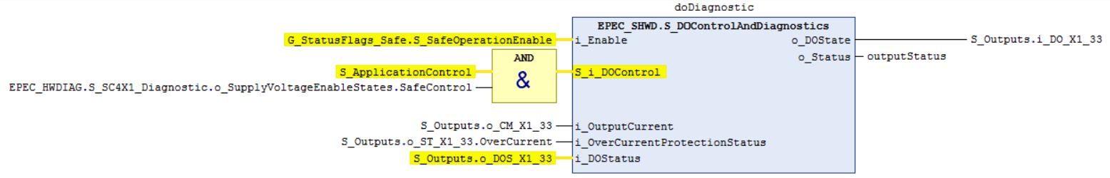
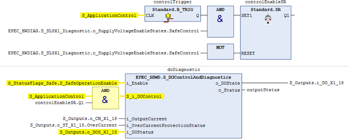
The o_SupplyVoltageEnableStates.SafeControl flag is used as control request condition. It is not used in i_Enable input condition because this would disable output pin's diagnostics (e.g. external voltage detection). |
Following are examples of how to use HW diagnostic states with output control and diagnostics.
Option 1:
If supply voltage is out of safe control range, output control is set off
If supply voltage goes back to valid range, output control is set back on assuming that application control request is still active
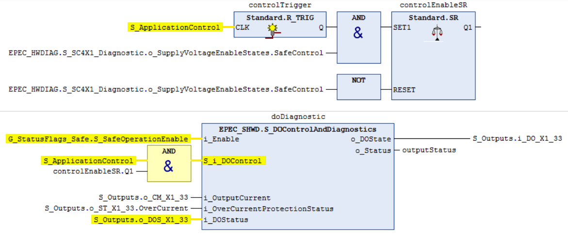
Option 2:
If supply voltage is out of safe control range, output control is set off
If supply voltage goes back to valid range, rising edge of application request is required before output is set back on
MultiTool Creator code template uses S_SL8X1_Diagnostic (PRG) for SL8X1 unit's HW diagnostics.
See the PRG's manual for description on diagnostics and functionalities that are implemented by library.
This guide gives application examples on controls that are required to be performed by the application and also information on status indications that are provided for application controls.
Code template
|
|
S_o_DiagStatusOk affects MultiTool Creator code template's status G_StatusFlags_Safe.S_SafeOperationEnable
S_SafeOperationEnable is set FALSE if diagnostic error is detected in a functionalities which affect the S_o_DiagStatusOk. The application shall use S_SafeOperationEnable as a condition for safety related controls. |
When code template is generated by MultiTool Creator, the S_Main PRG contains example on application controls for the HW diagnostic inputs.
Safety switch startup test
Safety switch startup test is triggered by application. This allows the application to delay the startup test execution, if necessary.
Delaying the startup test can be required in system condition where the supply voltage fluctuates after system bootup.
|
The startup test will perform tests for the safety switch and also check for external voltages in outputs. See product's safety manual for more information. |
|
If application wants to avoid FW error during startup test due to the output's external voltage, the application can diagnose the outputs before triggering the startup test. See How to control DO & DO ECO for information on how to diagnose the output with DOS status. |
Startup test is started by setting following input TRUE:
|
Code: |
|
EPEC_HWDIAG.S_SL8X1_Diagnostic.i_SwitchStartupTestEnable := TRUE; |
Output group control
|
|
The default state of the output group control is OFF. Control conditions are application specific. |
|
|
Output group control can only be activated once. After output group deactivation, reboot is required for output group re-activation. |
|
|
Output group control is automatically deactivated in following conditions:
|
|
After the startup test has been executed and output group is activated, the external voltage diagnostic in output pins is application's responsibility. See How to control DO & DO ECO for information on how to diagnose the outputs with DOS status. |
Startup test execution is required before output group can be controlled. The code template's S_SafeOperationEnable status is not TRUE before output group diagnostic is enabled in library.
The output group diagnostic's enable status can also be read from following variable:
EPEC_HWDIAG.S_SL8X1_Diagnostic.o_DiagEnableStates.OutputGroup1_Diagnostic_Enable
The following is an example of output group control
|
Code: |
|
EPEC_HWDIAG.S_SL8X1_Diagnostic.i_OutputGroup1Control := G_StatusFlags_Safe.S_SafeOperationEnable; |
The current state of control can be read by the application from the following variable:
EPEC_HWDIAG.S_SL8X1_Diagnostic.S_o_OutputGroup1Control
Reference output control(s)
HW diagnostic library supports up to two REF outputs (REF A and REF B). Both REF outputs support 5V or 10V REF mode.
The MultiTool Creator's code template initializes automatically the REF output in use and mode parameters based on functional version's HW assembly.
| Product | REF A | REF B |
|
SL8X1-01 |
In use: TRUE |
In use: TRUE |
|
|
The default state of the REF output control is TRUE. Control conditions are application specific. |
|
|
When REF output's in use is FALSE, the corresponding REF output is not available in product. |
Product has REFOUT switch which is secondary shutdown path if hardware fault prevents REF output control request to disable REF voltage.
The HW diagnostic library automatically controls REFOUT switch off if persistent overvoltage error is detected from either of the REF outputs.
Following is example of REFOUT switch control.
|
Code: |
|
EPEC_HWDIAG.S_SL8X1_Diagnostic.i_RefoutSwitchControl := TRUE; |
Following is example of REF A and REF B control.
|
Code: |
|
EPEC_HWDIAG.S_SL8X1_Diagnostic.i_RefAVoltageControl := TRUE; |
The HW diagnostic library has automatic enable logic for REF output's diagnostic and control based on control unit's supply voltage.
This is done to protect the hardware and to prevent unnecessary errors.
|
|
See S_SL8X1_Diagnostic (PRG) for supply voltage limits for REF output diagnostic and control conditions. |
If application's REF output control request is TRUE, the library automatically resumes REF control after supply voltage resumes in normal levels.
The state of REF output diagnostic enable can be read by the application from the following variables:
EPEC_HWDIAG.S_SL8X1_Diagnostic.o_DiagEnableStates.REF_A_Diagnostic_Enable
EPEC_HWDIAG.S_SL8X1_Diagnostic.o_DiagEnableStates.REF_B_Diagnostic_Enable
The state of REF output's control can be read by the application from the following variables:
EPEC_HWDIAG.S_SL8X1_Diagnostic.S_o_RefAControl
EPEC_HWDIAG.S_SL8X1_Diagnostic.S_o_RefBControl
The measured voltage of REF output can be read by the application from the following variables:
EPEC_HWDIAG.S_SL8X1_Diagnostic.S_o_RefAVoltage
EPEC_HWDIAG.S_SL8X1_Diagnostic.S_o_RefBVoltage
|
|
If REF output's REF_<X>_Diagnostic_Enable is FALSE (e.g. due to the supply voltage limits), the REF outputs OutputValid flag is FALSE and this is not considered error. The REF output has error only in situation where OutputValid is FALSE AND diagnostic has been enabled. |
The validity of REF output's measurement can be checked by the application from the following variables:
EPEC_HWDIAG.S_SL8X1_Diagnostic.o_RefAControlStatus.OutputValid
EPEC_HWDIAG.S_SL8X1_Diagnostic.o_RefBControlStatus.OutputValid
Application output control conditions
The HW diagnostic library has status flags for application to indicate when supply voltage is in range where output controls can be used/activated.
The supply voltage enable flags are found from library output EPEC_HWDIAG.S_SL8X1_Diagnostic.o_SupplyVoltageEnableStates.
These statuses are not affected by the supply voltage's error diagnostics limits.
|
|
See S_SL8X1_Diagnostic (PRG) for output control's supply voltage limits. |
|
|
For in depth guides on output control and diagnostics see Safety project How to guides. For example: |
|
|
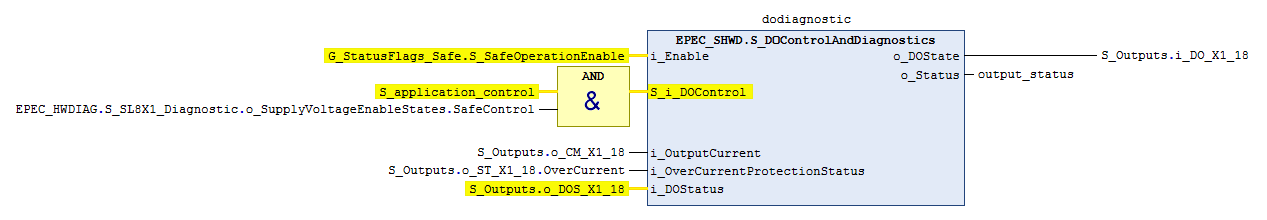
The o_SupplyVoltageEnableStates.SafeControl flag is used as control request condition. It is not used in i_Enable input condition because this would disable output pin's diagnostics (e.g. external voltage detection). |
Following are examples of how to use HW diagnostic states with output control and diagnostics.
Option 1:
If supply voltage is out of safe control range, output control is set off
If supply voltage goes back to valid range, output control is set back on assuming that application control request is still active
Option 2:
If supply voltage is out of safe control range, output control is set off
If supply voltage goes back to valid range, rising edge of application request is required before output is set back on
MultiTool Creator code template uses S_SM8X1_Diagnostic (PRG) for SM8X1 unit's HW diagnostics.
See the PRG's manual for description on diagnostics and functionalities that are implemented by library.
This guide gives application examples on controls that are required to be performed by the application and also information on status indications that are provided for application controls.
Code template
|
|
S_o_DiagStatusOk affects MultiTool Creator code template's status G_StatusFlags_Safe.S_SafeOperationEnable
S_SafeOperationEnable is set FALSE if diagnostic error is detected in a functionalities which affect the S_o_DiagStatusOk. The application shall use S_SafeOperationEnable as a condition for safety related controls. |
When code template is generated by MultiTool Creator, the S_Main PRG contains example on application controls for the HW diagnostic inputs.
Safety switch startup test
Safety switch startup test is triggered by application. This allows the application to delay the startup test execution, if necessary.
Delaying the startup test can be required in system condition where the supply voltage fluctuates after system bootup.
|
The startup test will perform tests for the safety switch and also check for external voltages in outputs. See product's safety manual for more information. |
|
If application wants to avoid FW error during startup test due to the output's external voltage, the application can diagnose the outputs before triggering the startup test. See How to control DO & DO ECO for information on how to diagnose the output with DOS status. |
Startup test is started by setting following input TRUE:
|
Code: |
|
EPEC_HWDIAG.S_SM8X1_Diagnostic.i_SwitchStartupTestEnable := TRUE; |
Output group control
|
|
The default state of the output group control is OFF. Control conditions are application specific. |
|
|
Output group control can only be activated once. After output group deactivation, reboot is required for output group re-activation. |
|
|
Output group control is automatically deactivated in following conditions:
|
|
After the startup test has been executed and output group is activated, the external voltage diagnostic in output pins is application's responsibility. See How to control DO & DO ECO for information on how to diagnose the outputs with DOS status. |
Startup test execution is required before output group can be controlled. The code template's S_SafeOperationEnable status is not TRUE before output group diagnostic is enabled in library.
The output group diagnostic's enable status can also be read from following variable:
EPEC_HWDIAG.S_SM8X1_Diagnostic.o_DiagEnableStates.OutputGroup1_Diagnostic_Enable
The following is an example of output group control
|
Code: |
|
EPEC_HWDIAG.S_SM8X1_Diagnostic.i_OutputGroup1Control := G_StatusFlags_Safe.S_SafeOperationEnable; |
The current state of control can be read by the application from the following variable:
EPEC_HWDIAG.S_SM8X1_Diagnostic.S_o_OutputGroup1Control
Reference output control(s)
HW diagnostic library supports up to two REF outputs (REF A and REF B). Both REF outputs support 5V or 10V REF mode.
The MultiTool Creator's code template initializes automatically the REF output in use and mode parameters based on functional version's HW assembly.
| Product | REF A | REF B |
|
SM8X1-02 |
In use: FALSE |
In use: FALSE |
|
|
The default state of the REF output control is TRUE. Control conditions are application specific. |
|
|
When REF output's in use is FALSE, the corresponding REF output is not available in product. |
Product has REFOUT switch which is secondary shutdown path if hardware fault prevents REF output control request to disable REF voltage.
The HW diagnostic library automatically controls REFOUT switch off if persistent overvoltage error is detected from either of the REF outputs.
Following is example of REFOUT switch control.
|
Code: |
|
EPEC_HWDIAG.S_SM8X1_Diagnostic.i_RefoutSwitchControl := TRUE; |
Following is example of REF A and REF B control.
|
Code: |
|
EPEC_HWDIAG.S_SM8X1_Diagnostic.i_RefAVoltageControl := TRUE; |
The HW diagnostic library has automatic enable logic for REF output's diagnostic and control based on control unit's supply voltage.
This is done to protect the hardware and to prevent unnecessary errors.
|
|
See S_SM8X1_Diagnostic (PRG) for supply voltage limits for REF output diagnostic and control conditions. |
If application's REF output control request is TRUE, the library automatically resumes REF control after supply voltage resumes in normal levels.
The state of REF output diagnostic enable can be read by the application from the following variables:
EPEC_HWDIAG.S_SM8X1_Diagnostic.o_DiagEnableStates.REF_A_Diagnostic_Enable
EPEC_HWDIAG.S_SM8X1_Diagnostic.o_DiagEnableStates.REF_B_Diagnostic_Enable
The state of REF output's control can be read by the application from the following variables:
EPEC_HWDIAG.S_SM8X1_Diagnostic.S_o_RefAControl
EPEC_HWDIAG.S_SM8X1_Diagnostic.S_o_RefBControl
The measured voltage of REF output can be read by the application from the following variables:
EPEC_HWDIAG.S_SM8X1_Diagnostic.S_o_RefAVoltage
EPEC_HWDIAG.S_SM8X1_Diagnostic.S_o_RefBVoltage
|
|
If REF output's REF_<X>_Diagnostic_Enable is FALSE (e.g. due to the supply voltage limits), the REF outputs OutputValid flag is FALSE and this is not considered error. The REF output has error only in situation where OutputValid is FALSE AND diagnostic has been enabled. |
The validity of REF output's measurement can be checked by the application from the following variables:
EPEC_HWDIAG.S_SM8X1_Diagnostic.o_RefAControlStatus.OutputValid
EPEC_HWDIAG.S_SM8X1_Diagnostic.o_RefBControlStatus.OutputValid
Application output control conditions
The HW diagnostic library has status flags for application to indicate when supply voltage is in range where output controls can be used/activated.
The supply voltage enable flags are found from library output EPEC_HWDIAG.S_SM8X1_Diagnostic.o_SupplyVoltageEnableStates.
These statuses are not affected by the supply voltage's error diagnostics limits.
|
|
See S_SM8X1_Diagnostic (PRG) for output control's supply voltage limits. |
|
|
For in depth guides on output control and diagnostics see Safety project How to guides. For example: |
|
|
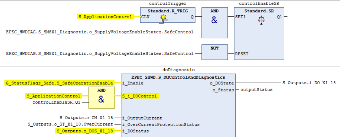
The o_SupplyVoltageEnableStates.SafeControl flag is used as control request condition. It is not used in i_Enable input condition because this would disable output pin's diagnostics (e.g. external voltage detection). |
Following are examples of how to use HW diagnostic states with output control and diagnostics.
Option 1:
If supply voltage is out of safe control range, output control is set off
If supply voltage goes back to valid range, output control is set back on assuming that application control request is still active
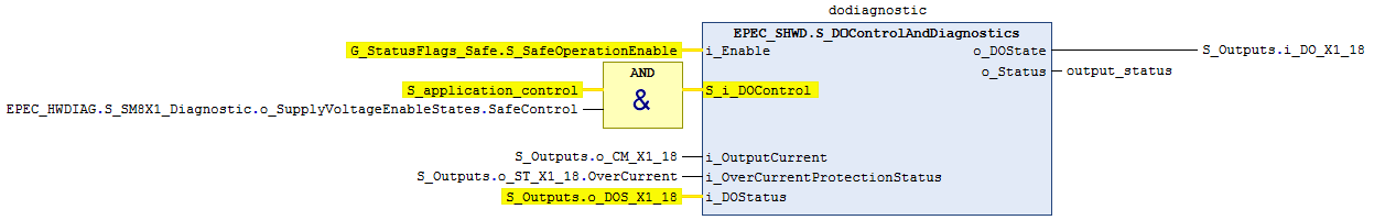
Option 2:
If supply voltage is out of safe control range, output control is set off
If supply voltage goes back to valid range, rising edge of application request is required before output is set back on
SafeSSeriesHardware library
SafeSC4XDiagnostic library
SafeSL8XDiagnostic library
SafeSM8XDiagnostic library
SP10
S_SC52_Diagnostic (PRG)
S_SL84_Diagnostic (PRG)
S_EC44_Diagnostic (PRG)
SP19
S_SC4X1_Diagnostic (PRG)
S_SL8X1_Diagnostic (PRG)
S_SM8X1_Diagnostic (PRG)
Source file topic100548.htm
Last updated 4-Sep-2025