![]()
A parameter error is diagnosed if:
• Init method is not called before the main FB call OR
• i_pEventCode = 0 OR
• i_pEventCodeCh2 = 0
Supported platforms: CODESYS 3.5, CODESYS 3.5 SAFETY, CODESYS 3.5 SP19 SAFETY
This function block validates a digital status by comparing two digital statuses. The channel 2 state can be inverted.
Init method is used to initialize the necessary static calculation parameters for the function block instance.
The method shall be called at least once before the actual function block can be called, i.e. at the application initialization phase.
The method checks the validity of input parameters. However, none of the function block outputs are affected by the initialization.
|
|
A parameter error is diagnosed if: • Init method is not called before the main FB call OR • i_pEventCode = 0 OR • i_pEventCodeCh2 = 0
|
|
Parameter |
Data type |
Unit |
Range |
Description |
|
S_i_InvertedCh2 |
SAFEBOOL |
- |
- |
Input channel 2 is inverted. |
|
S_i_SafeOutputState |
SAFEBOOL |
- |
- |
Safe output state in case of error. |
|
S_i_DiagnosticDelay |
SAFEUINT |
ms |
- |
Delay time for diagnostics. |
|
i_pEventCode |
POINTER TO EventCode |
- |
≠ 0 |
Pointer to application variable which is type EventCode. Used with POUs that handle signal data. |
|
i_pEventCodeCh2 |
POINTER TO EventCode |
- |
≠ 0 |
Pointer to application variable which is type EventCode. Used with POUs that handle validation signal data. |
|
TRUE: All initialization parameters ok. |
|
FALSE: Error in initialization parameter(s). |
The function block writes S_i_Ch1State state to S_o_Output and sets o_Status.OutputValid state TRUE if
• The control is enabled, i.e. i_Enable is TRUE AND
• No fault (including initialization) has been diagnosed
The input is considered as valid if
• S_i_InvertedCh2 is TRUE and channel states differ OR
• S_i_InvertedCh2 is FALSE and channel states are equal.
The block sets o_Status.OutputValid state TRUE if signals are valid and operation is enabled, i.e. i_Enable is TRUE
If channel states mismatch continuously over S_i_DiagnosticDelay time, then
• S_o_Output is set to given safe value,
• Status o_Status.OutputValid is set FALSE,
• The corresponding Error bit in o_Status variable is set TRUE, and
• The corresponding EventID is set to i_pEventCode
All function block statuses, including errors are reset on rising edge of i_Enable.
|
Input variable name |
Data type |
Range |
Description |
|
i_Enable |
BOOL |
- |
Enables validation functionality |
|
S_i_Ch1State |
SAFEBOOL |
- |
Input channel 1 (signal) state |
|
S_i_Ch2State |
SAFEBOOL |
- |
Input channel 2 (validation) state |
|
Output variable name |
Data type |
Range |
Description |
|
S_o_Output |
SAFEBOOL |
- |
Validated input status |
|
o_Status |
Status |
- |
Status of output value. See Status structure. |
See Diagnostic Interface library description of error status and event code functionality.
|
Conditions |
S_o_Output value |
o_Status. OutputValid |
o_Status error status |
Event code FunctionID |
Event code EventID |
|
i_Enable TRUE AND init parameter error AND i_pEventCode valid |
S_i_Safe OutputState |
FALSE |
ParameterError |
VALIDATE_DI |
PARAMETER_ERROR |
|
i_Enable TRUE AND init parameter error AND |
S_i_Safe OutputState |
FALSE |
ParameterError |
- |
- |
|
i_Enable rises AND init parameters ok AND inputs match |
S_i_Ch1State |
TRUE |
- |
NO_FUNC |
NO_ERROR |
|
i_Enable TRUE AND init parameters ok AND inputs mismatch |
S_i_Safe OutputState |
FALSE |
ValueMismatch |
VALIDATE_DI |
DATA_MISMATCH |
|
|
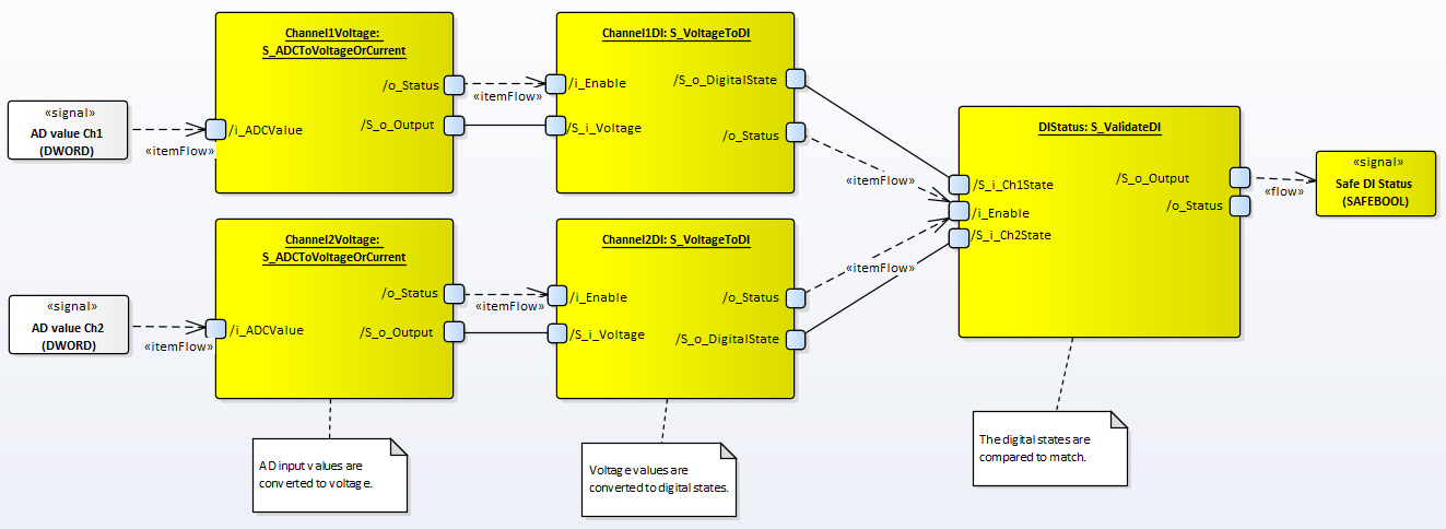
Input ADC value is first converted to voltage (mV) with S_ADCToVoltageOrCurrent function block. The voltage value is then converted to DI status with S_VoltageToDI function block. Conversion and DI status are included in MultiTool Creator code template. |
|
|
Validation is NOT included in MultiTool Creator code template. |
|
Safe definitions: |
|
(* Voltage conversion FBs (generated by MT) left out of example *)
(* DI conversion FBs *) S_1_09_ToDI: EPEC_SC.S_VoltageToDI; // generated by MT S_1_10_ToDI: EPEC_SC.S_VoltageToDI; // generated by MT
(* DI statuses from AI values, converted with S_VoltageToDI *) S_DI_1_09_State: SAFEBOOL := FALSE; // generated by MT S_DI_1_10_State: SAFEBOOL := FALSE; // generated by MT
EC_DI1_09: EPEC_DITF.EventCode; // these event codes are generated by MT EC_DI1_10: EPEC_DITF.EventCode; // and used by conversions AND validation
// validation data is not generated by MT S_ValidDI1: EPEC_SDV.S_ValidateDI; DIValidationStatus: EPEC_SDV.Status; S_ValidDIState: SAFEBOOL := FALSE; // validated DI status
|
|
Init at safe PRG: |
|
EC_DI1_09.DeviceID := DeviceIDs.DigitalInput; EC_DI1_09.ChannelID := ChannelIDs.Ch1; EC_DI1_09.FunctionID := EPEC_DITF.FunctionIDs.NO_FUNC; EC_DI1_09.EventID := EPEC_DITF.ErrorIDs.NO_ERROR;
EC_DI1_10.DeviceID := DeviceIDs.DigitalInput; EC_DI1_10.ChannelID := ChannelIDs.Ch2; EC_DI1_10.FunctionID := EPEC_DITF.FunctionIDs.NO_FUNC; EC_DI1_10.EventID := EPEC_DITF.ErrorIDs.NO_ERROR;
S_ValidDI1.Init( S_i_InvertedCh2 := FALSE, (* Channel 2 is not inverted *) S_i_DiagnosticDelay := EPEC_HW.Constants.G_DIGITAL_INPUT_DIAGNOSTIC_DELAY, (* Error delay (ms) *) S_i_SafeOutputState := EPEC_HW.Constants.G_DIGITAL_INPUT_SAFE_STATE, (* Safe state for output *) i_pEventCode := ADR(EC_DI1_09), (* Event code pointer for FB *) i_pEventCodeCh2 := ADR(EC_DI1_10) (* Event code pointer for FB *) );
|
|
Code at safe PRG: |
|
S_ValidDI1( i_Enable := S_1_09_ToDI.o_Status.OutputValid AND S_1_10_ToDI.o_Status.OutputValid, S_i_Ch1State := S_DI_1_09_State, S_i_Ch2State := S_DI_1_10_State, o_Status => DIValidationStatus, S_o_Output => S_ValidDIState (* Validated safe DI status *) );
|
S_VoltageToDI (FB)
S_ValidateAI (FB)
Source file topic100385.htm
Last updated 4-Sep-2025