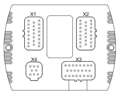
The four connectors are placed in the control unit according to the following figure:
The following table lists the pins according their pin number. Other columns offer quick information about the pin and links for more information.
The group column:
* smaller case characters indicate the input groups (the pins in the same group have the same configurations)
UPPER CASE CHARACTERS indicate the output groups (the pins in the same group have the same configurations)
Connector 1:
Pin number |
Pin type |
Details |
Group* |
Current / Voltage |
Description |
First row: |
|||||
X1.1 |
10 kΩ GND |
|
Nominal current 3 A |
|
|
X1.2 |
10 kΩ GND |
|
Nominal current 3 A |
|
|
X1.3 |
0,1 Ω GND |
a |
0-2 A |
|
|
X1.4 |
Cross connected FB/AI |
|
a |
|
|
X1.5 |
0,1 Ω GND |
b |
0-2 A |
|
|
X1.6 |
Cross connected FB/AI |
b |
|
||
X1.7 |
10 kΩ +24 V |
A |
Nominal current 3 A |
|
|
X1.8 |
|
10 kΩ +24 V |
A |
Nominal current 3 A |
|
Second row: |
|||||
X1.9 |
10 kΩ GND |
B |
Nominal current 3 A |
|
|
X1.10 |
0,1 Ω GND |
c |
0-2 A |
|
|
X1.11 |
10 kΩ +24 V |
|
Nominal current 3 A |
|
|
X1.12 |
GND |
|
|
||
X1.13 |
10 kΩ +24 V |
|
Nominal current 3 A |
|
|
X1.14 |
0,1 Ω GND |
d |
0-2 A |
|
|
X1.15 |
10 kΩ GND |
B |
Nominal current 3 A |
|
|
Third row: |
|||||
X1.16 |
10 kΩ GND |
B |
Nominal current 3 A |
|
|
X1.17 |
Cross connected FB/AI |
|
c |
|
|
X1.18 |
10 kΩ GND |
B |
Nominal current 3 A |
|
|
X1.19 |
10 kΩ GND |
B |
Nominal current 3 A |
|
|
X1.20 |
0,1 Ω GND |
e |
0-2 A |
|
|
X1.21 |
Cross connected FB/AI |
|
e |
|
|
X1.22 |
Cross connected FB/AI |
|
d |
|
|
X1.23 |
10 kΩ GND |
B |
Nominal current 3 A |
|
|
Connector 2:
Pin number |
Pin type |
Details |
Group* |
Current / Voltage |
Description |
First row: |
|||||
X2.1 |
10 kΩ +24 V |
|
Nominal current 3 A |
|
|
X2.2 |
10 kΩ +24 V |
|
Nominal current 3 A |
|
|
X2.3 |
0,1 Ω GND |
f |
0-2 A |
|
|
X2.4 |
Cross connected FB/AI |
|
f |
|
|
X2.5 |
0,1 Ω GND |
g |
0-2 A |
|
|
X2.6 |
Cross connected FB/AI |
g |
|
||
X2.7 |
10 kΩ +24 V |
B |
Nominal current 3 A |
|
|
X2.8 |
|
10 kΩ +24 V |
B |
Nominal current 3 A |
|
Second row: |
|||||
X2.9 |
10 kΩ +24 V |
A |
Nominal current 3 A |
|
|
X2.10 |
0,1 Ω GND |
h |
0-2 A |
|
|
X2.11 |
10 kΩ +24 V |
|
Nominal current 3 A |
|
|
X2.12 |
GND |
|
|
||
X2.13 |
10 kΩ +24 V |
|
Nominal current 3 A |
|
|
X2.14 |
0,1 Ω GND |
i |
0-2 A |
|
|
X2.15 |
10 kΩ +24 V |
A |
Nominal current 3 A |
|
|
Third row: |
|||||
X2.16 |
10 kΩ +24 V |
A |
Nominal current 3 A |
|
|
X2.17 |
Cross connected FB/AI |
|
h |
|
|
X2.18 |
10 kΩ +24 V |
A |
Nominal current 3 A |
|
|
X2.19 |
10 kΩ +24 V |
A |
Nominal current 3 A |
|
|
X2.20 |
0,1 Ω GND |
j |
0-2 A |
|
|
X2.21 |
Cross connected FB/AI |
|
j |
|
|
X2.22 |
Cross connected FB/AI |
|
i |
|
|
X2.23 |
10 kΩ +24 V |
A |
Nominal current 3 A |
|
|
Connector 3:
Pin number |
Pin type |
Details |
Group* |
Current / Voltage |
Description |
First row: |
|||||
X3.1 |
AUX OUT (U = Uin) |
10 kΩ GND |
max. 4 A |
Shared current with pin 3.9 |
|
X3.2 |
|
|
+5 V 270 mA |
|
|
X3.3 |
2,2 kΩ +5 V / 220 Ω GND |
|
0-5 V / 0-22 mA
|
|
|
X3.4 |
82 kΩ GND / 220 Ω GND |
0-5 V / 0-22 mA |
|
||
X3.5 |
82 kΩ GND / 220 Ω GND |
|
0-5 V / 0-22 mA |
|
|
X3.6 |
82 kΩ GND / 220 Ω GND |
0-5 V / 0-22 mA |
|
||
X3.7 |
82 kΩ GND / 220 Ω GND |
0-5 V / 0-22 mA |
|
||
X3.8 |
82 kΩ GND / 220 Ω GND |
0-5 V / 0-22 mA |
|
||
Second row: |
|||||
X3.9 |
AUX OUT (U = Uin) |
10 kΩ GND |
max. 4 A |
Shared current with pin 3.1 |
|
X3.10 |
GND |
|
|
|
|
X3.11 |
GND |
|
|
|
|
X3.12 |
GND |
|
|
|
|
X3.13 |
GND
|
|
|
||
X3.14 |
10 kΩ +5 V |
|
|
||
X3.15 |
|
|
|
|
|
Third row: |
|||||
X3.16 |
10 kΩ +5 V |
|
|
|
|
X3.17 |
10 kΩ +5 V |
|
|
|
|
X3.18 |
10 kΩ +5 V |
|
|
|
|
X3.19 |
10 kΩ +5 V |
|
|
|
|
X3.20 |
10 kΩ +5 V |
|
|
|
|
X3.21 |
10 kΩ +5 V |
|
|
|
|
X3.22 |
10 kΩ +5 V |
|
|
|
|
X3.23 |
10 kΩ +5 V |
|
|
|
|
Connector 4:
Pin number |
Pin type |
Details |
Group* |
Current / Voltage |
Description |
X4.1 |
GND |
Supply GND |
|
|
|
X4.2 |
CAN1 H |
|
|
|
|
X4.3 |
GND |
Supply GND |
|
|
|
X4.4 |
|
|
|
|
|
X4.5 |
|
|
|
|
|
X4.6 |
CAN1 L |
|
|
|
|
X4.7 |
CAN2 H |
|
|
|
|
X4.8 |
CAN2 L |
|
|
|
|