![]()
The FB uses internally SafeProportionalValveControl librarys FBs:
S_EndAttenuation
S_PVGValveController
Supported platforms: CODESYS 3.5
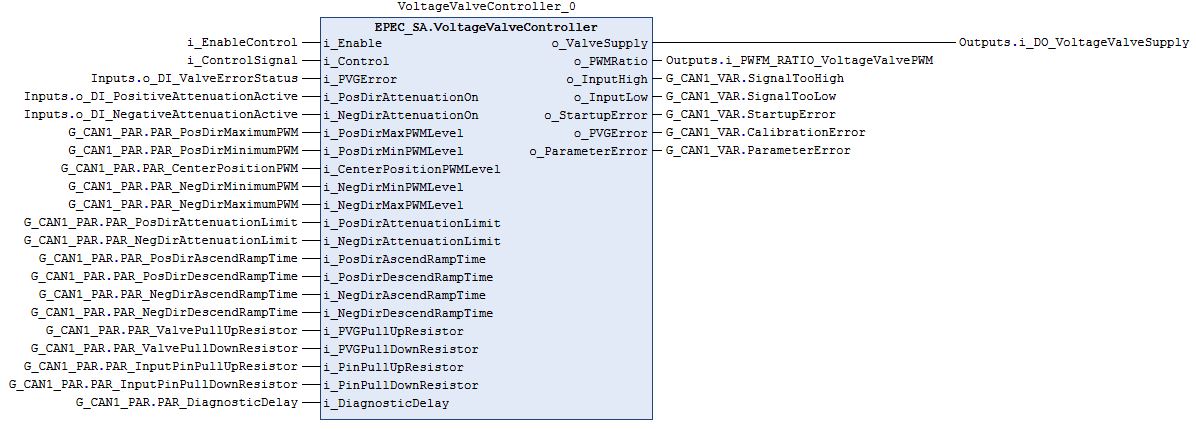
This FB handles Danfoss PVG32 voltage controlled proportional valve.
The FB includes end attenuation and ramp.
A startup error is diagnosed if control is requested on the rising edge of i_Enable.
The output control signal is set to zero if i_Enable is FALSE, parameter error is diagnosed or startup error is diagnosed.
All internal FB initializations are done on the rising edge of i_Enable.
All errors are reset on the rising edge of i_Enable.
|
The FB uses internally SafeProportionalValveControl librarys FBs: S_EndAttenuation S_PVGValveController |
|
Following parameters are taken into use at the rising edge of i_Enable: - i_PosDirMaxPWMLevel - i_PosDirMinPWMLevel - i_CenterPositionPWMLevel - i_NegDirMinPWMLevel - i_NegDirMaxPWMLevel - i_PosDirAttenuationLimit - i_NegDirAttenuationLimit - i_PosDirAscendRampTime - i_PosDirDescendRampTime - i_NegDirAscendRampTime - i_NegDirDescendRampTime - i_PVGPullUpResistor - i_PVGPullDownResistor - i_PinPullUpResistor - i_PinPullDownResistor - i_DiagnosticDelay + Any initialized event code. |
Input variable name |
Data type |
Range |
Description |
i_Enable |
BOOL |
FALSE/TRUE |
Enables controlling of the PWM outputs |
i_Control |
INT |
0..10000 |
Control signal from e.g. joystick. |
i_PVGError |
BOOL |
FALSE/TRUE |
Error signal from PVG valve. |
i_PosDirAttenuationOn |
BOOL |
FALSE/TRUE |
Positive direction end attenuation sensor activity status. |
i_NegDirAttenuationOn |
BOOL |
FALSE/TRUE |
Negative direction end attenuation sensor activity status. |
i_PosDirMaxPWMLevel |
UINT |
0..1000‰ |
Output voltage(PWM) level corresponding the value *i_Control* = 10000. Permil from unit's supply voltage. |
i_PosDirMinPWMLevel |
UINT |
0..1000‰ |
Output voltage(PWM) level corresponding the value *i_Control* = 1. Permil from unit's supply voltage. |
i_CenterPositionPWMLevel |
UINT |
0..1000‰ |
Output voltage(PWM) level corresponding the value *i_Control* = 0. Permil from unit's supply voltage. |
i_NegDirMinPWMLevel |
UINT |
0..1000‰ |
Output voltage(PWM) level corresponding the value *i_Control* = -1. Permil from unit's supply voltage. |
i_NegDirMaxPWMLevel |
UINT |
0..1000‰ |
Output voltage(PWM) level corresponding the value *i_Control* = -10000. Permil from unit's supply voltage. |
i_PosDirAttenuationLimit |
UINT |
0..100% |
Positive direction attenuation limit. Percentage from maximum control value 10000. |
i_NegDirAttenuationLimit |
UINT |
0..100% |
Negative direction attenuation limit. Percentage from maximum control value -10000. |
i_PosDirAscendRampTime |
UINT |
- |
Time (ms) of o_PosDirPWMRatio signal to change from center to positive max (0->10000). |
i_PosDirDescendRampTime |
UINT |
- |
Time (ms) of o_PosDirPWMRatio signal to change from positive max to center (10000->0). |
i_NegDirAscendRampTime |
UINT |
- |
Time (ms) of o_NegDirPWMRatio signal to change from center to negative min (0->-10000). |
i_NegDirDescendRampTime |
UINT |
- |
Time (ms) of o_NegDirPWMRatio signal to change from negative min to center (-10000->0). |
i_PVGPullUpResistor |
UDINT |
- |
PVG valve pull up resistor (Ohm). |
i_PVGPullDownResistor |
UDINT |
- |
PVG valve pull down resistor (Ohm). |
i_PinPullUpResistor |
UDINT |
- |
Control unit PWM pin pull up resistor (Ohm). |
i_PinPullDownResistor |
UDINT |
- |
Control unit PWM pin pull down resistor (Ohm). |
i_DiagnosticDelay |
UINT |
- |
Diagnostic delay (ms) for PVG valve error signal. |
Output variable name |
Data type |
Range |
Description |
o_ValveSupply |
BOOL |
FALSE/TRUE |
Control PVG valve supply. |
o_PWMRatio |
DWORD |
HW specific |
Output value to PWM pin. |
o_InputHigh |
BOOL |
FALSE/TRUE |
i_Control too high. |
o_InputLow |
BOOL |
FALSE/TRUE |
i_Control too low. |
o_StartupError |
BOOL |
FALSE/TRUE |
Control request on already when i_Enable rises. |
o_PVGError |
BOOL |
FALSE/TRUE |
Valve error output status. |
o_ParameterError |
BOOL |
FALSE/TRUE |
Incorrect parameter value in any of the monitored parameters. |
This optional method sets pointers for event codes.
Input variable name |
Data type |
Description |
i_Enable |
BOOL |
Enable operation. |
i_pEventCode |
POINTER TO EPEC_DITF.EventCode |
Pointer to signal event code value provided by the application. |
i_pEventCodePosDir |
POINTER TO EPEC_DITF.EventCode |
Pointer to signal event code value provided by the application. |
i_pEventCodeNegDir |
POINTER TO EPEC_DITF.EventCode |
Pointer to signal event code value provided by the application. |
See Diagnostic Interface library description of error status and event code functionality.
|
FunctionID and EventID are only set if EventCode is used. |
|
A parameter error is diagnosed if:
|
Conditions |
o_PWMRatio |
Output error set TRUE |
Event code FunctionID |
Event code EventID |
i_Enable TRUE AND parameter error AND i_pEventCode valid |
0 |
o_ParameterError |
depends on the parameter |
PARAMETER_ERROR |
i_Enable TRUE AND parameter
error AND |
0 |
o_ParameterError |
- |
- |
i_Enable rises AND parameters ok AND i_Control <> 0 |
0 |
o_StartupError |
PVG_CONTROLLER |
STARTUP_ERROR |
i_Enable TRUE AND init parameters ok AND i_Control within range |
PWM ratio |
- |
NO_FUNC |
NO_ERROR |
i_Enable TRUE AND init parameters ok AND i_Control > 10000 |
0 |
o_InputHigh |
END_ATTENUATION |
INPUT_TOO_HIGH |
i_Enable TRUE AND parameters ok AND i_Control < -10000 |
0 |
o_InputLow |
END_ATTENUATION |
INPUT_TOO_LOW |
i_Enable TRUE AND init parameters ok AND i_Control within range AND i_PVGError TRUE |
0 |
o_PVGError |
PVG_CONTROLLER |
PVG_VALVE_ERROR |
Source file topic100766.htm
Last updated 4-Sep-2025