![]()
The FB uses internally SafeProportionalValveControl librarys FBs:
S_EndAttenuation
S_LinearRamp
S_CurrentRequest
S_AdaptiveController
Supported platforms: CODESYS 3.5
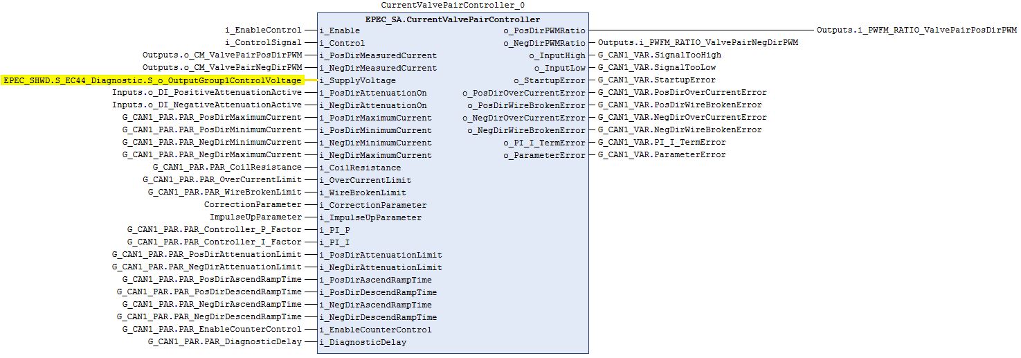
This FB handles current controlled proportional pair in products that do not have built-in controller.
The FB includes end attenuation, ramp and control curve progression.
A startup error is diagnosed if control is requested on the rising edge of i_Enable.
The output control signal is set to zero if i_Enable is FALSE, parameter error is diagnosed or startup error is diagnosed.
All internal FB initializations are done on the rising edge of i_Enable.
All errors are reset on the rising edge of i_Enable.
|
|
The FB uses internally SafeProportionalValveControl librarys FBs: S_EndAttenuation S_LinearRamp S_CurrentRequest S_AdaptiveController |
|
|
Following parameters are taken into use at the rising edge of i_Enable: - i_PosDirMaximumCurrent - i_PosDirMinimumCurrent - i_NegDirMinimumCurrent - i_NegDirMaximumCurrent - i_CoilResistance - i_OverCurrentLimit - i_WireBrokenLimit - i_pCorrectionParameter - i_pImpulseUpParameter - i_PI_P - i_PI_I - i_PosDirAttenuationLimit - i_NegDirAttenuationLimit - i_PosDirAscendRampTime - i_PosDirDescendRampTime - i_NegDirAscendRampTime - i_NegDirDescendRampTime - i_EnableCounterControl - i_DiagnosticDelay + Any initialized event code. |
|
Input variable name |
Data type |
Range |
Description |
|
i_Enable |
BOOL |
FALSE/TRUE |
Enables controlling of the PWM outputs |
|
i_Control |
INT |
-10000..10000 |
Control signal from e.g. joystick. |
|
i_PosDirMeasuredCurrent |
UDINT |
0..i_OverCurrentLimit |
Positive direction measured current (mA). |
|
i_NegDirMeasuredCurrent |
UDINT |
0..i_OverCurrentLimit |
Negative direction measured current (mA). |
|
i_SupplyVoltage |
DINT |
- |
Measured supply voltage (mV). |
|
i_PosDirAttenuationOn |
BOOL |
FALSE/TRUE |
Positive direction end attenuation sensor activity status. |
|
i_NegDirAttenuationOn |
BOOL |
FALSE/TRUE |
Negative direction end attenuation sensor activity status. |
|
i_PosDirMaximumCurrent |
UINT |
0..5000 |
Maximum current for valve that is controlled with positive control signal (mA) |
|
i_PosDirMinimumCurrent |
UINT |
0..5000 |
Minimum current for valve that is controlled with positive control signal (mA) |
|
i_NegDirMinimumCurrent |
UINT |
0..5000 |
Minimum current for valve that is controlled with negative control signal (mA) |
|
i_NegDirMaximumCurrent |
UINT |
0..5000 |
Maximum current for valve that is controlled with negative control signal (mA) |
|
i_CoilResistance |
UDINT |
> 0 |
Coil resistance (mΩ). |
|
i_OverCurrentLimit |
UINT |
> S_i_Wire BrokenLimit and <= 5000 |
Over current error limit (mA). |
|
i_WireBrokenLimit |
UINT |
0..5000 |
Wire broken error limit (mA). |
|
i_CorrectionParameter |
UINT |
- |
Correction factor parameter. 1000 is a neutral value. |
|
i_ImpulseUpParameter |
UINT |
- |
Impulse up factor parameter. Bigger value means higher impulse. 0 = use default impulse (1000). Impulse can be disabled with AdvancedInit method. |
|
i_PI_P |
UDINT |
>0* |
PI controller p-value. |
|
i_PI_I |
UDINT |
>0* |
PI controller i-value with two decimals, 1 = 0,01. |
|
i_PosDirAttenuationLimit |
UINT |
0..100% |
Positive direction attenuation limit. Percentage from maximum control value 10000. |
|
i_NegDirAttenuationLimit |
UINT |
0..100% |
Negative direction attenuation limit. Percentage from maximum control value -10000. |
|
i_PosDirAscendRampTime |
UINT |
- |
Time (ms) of o_PosDirPWMRatio signal to change from center to positive max (0->10000). |
|
i_PosDirDescendRampTime |
UINT |
- |
Time (ms) of o_PosDirPWMRatio signal to change from positive max to center (10000->0). |
|
i_NegDirAscendRampTime |
UINT |
- |
Time (ms) of o_NegDirPWMRatio signal to change from center to negative min (0->-10000). |
|
i_NegDirDescendRampTime |
UINT |
- |
Time (ms) of o_NegDirPWMRatio signal to change from negative min to center (-10000->0). |
|
i_EnableCounterControl |
BOOL |
FALSE/TRUE |
TRUE = o_PosDirPWMRatio and o_NegDirPWMRatio can be active at same time. |
|
i_DiagnosticDelay |
UINT |
- |
Diagnostic delay (ms) for overcurrent/wire broken errors. |
*Normally, value >0. PI-controller can be disabled by setting i_PI_P=0 and i_PI_I=0. This is required when finding the optimal i_CorrectionParameter value. See: S_AdaptiveController (FB), section Adjusting correction parameters.
|
Output variable name |
Data type |
Range |
Description |
|
o_PosDirPWMRatio |
DWORD |
HW specific |
Output value to PWM pin. Maximum value EPEC_HW.Constants.G_PWM_OUT_MAX_VALUE |
|
o_NegDirPWMRatio |
DWORD |
HW specific |
Output value to PWM pin. Maximum value EPEC_HW.Constants.G_PWM_OUT_MAX_VALUE |
|
o_InputHigh |
BOOL |
FALSE/TRUE |
i_Control too high. |
|
o_InputLow |
BOOL |
FALSE/TRUE |
i_Control too low. |
|
o_StartupError |
BOOL |
FALSE/TRUE |
Control request on already when i_Enable rises. |
|
o_PosDirOverCurrentError |
BOOL |
FALSE/TRUE |
Overcurrent error is detected. |
|
o_PosDirWireBrokenError |
BOOL |
FALSE/TRUE |
Wire broken error is detected. |
|
o_NegDirOverCurrentError |
BOOL |
FALSE/TRUE |
Overcurrent error is detected. |
|
o_NegDirWireBrokenError |
BOOL |
FALSE/TRUE |
Wire broken error is detected. |
|
o_PI_I_TermError |
BOOL |
FALSE/TRUE |
PI-controller I-term has reached it's limits. |
|
o_ParameterError |
BOOL |
FALSE/TRUE |
Incorrect parameter value in any of the monitored parameters. |
These optional methods set controlling parameters for positive and negative direction controllers.
|
Input variable name |
Data type |
Range |
Description |
|
i_Enable |
BOOL |
FALSE/TRUE |
Enable operation. |
|
i_CurrentChangeSpeed |
UINT |
>0 |
Current change speed mA/ms. |
|
i_UseImpulse |
BOOL |
FALSE/TRUE |
Impulse is used when current request changes more than i_ParStep. |
|
i_LearnOn |
BOOL |
FALSE/TRUE |
Adaptive controller learning, yet to be implemented. |
|
i_StartImpulseTime |
UINT |
- |
How long start impulse is active. Parameter affects only if i_AutomaticStartImpulse is false |
|
i_AutomaticStartImpulse |
BOOL |
FALSE/TRUE |
Controller automatically set start impulse when current request is deviated from 0. |
This optional method can be used for setting an array of correction and impulse parameters for controllers.
|
Input variable name |
Data type |
Range |
Description |
|
i_Enable |
BOOL |
FALSE/TRUE |
Enable operation. |
|
i_pCorrectionParameters |
POINTER TO UINT |
>0 |
Pointer to first correction factor parameter. |
|
i_pImpulseUpParameters |
POINTER TO UINT |
>0 |
Pointer to first impulse up factor parameter. |
|
i_pImpulseDownParameters |
POINTER TO UINT |
>0 |
Pointer to first impulse down factor parameter. |
|
i_ParameterCount |
UINT |
- |
Parameter count. |
|
i_ParStep |
UINT |
>0 |
Difference (mA) between consecutive correction factor parameters. |
This optional method sets pointers for event codes.
|
Input variable name |
Data type |
Description |
|
i_Enable |
BOOL |
Enable operation. |
|
i_pEventCode |
POINTER TO EPEC_DITF.EventCode |
Pointer to signal event code value provided by the application. |
|
i_pEventCodePosDir |
POINTER TO EPEC_DITF.EventCode |
Pointer to signal event code value provided by the application. |
|
i_pEventCodeNegDir |
POINTER TO EPEC_DITF.EventCode |
Pointer to signal event code value provided by the application. |
See Diagnostic Interface library description of error status and event code functionality.
|
|
FunctionID and EventID are only set if EventCode is used. |
|
|
A parameter error is diagnosed if:
|
|
Conditions |
o_PWMRatio |
Output error set TRUE |
Event code FunctionID |
Event code EventID |
|
i_Enable TRUE AND parameter error AND i_pEventCode valid |
0 |
o_ParameterError |
depends on the parameter |
PARAMETER_ERROR |
|
i_Enable TRUE AND parameter error AND |
0 |
o_ParameterError |
- |
- |
|
i_Enable rises AND parameters ok AND i_Control <> 0 |
0 |
o_StartupError |
CURRENT CONTROLLER |
STARTUP_ERROR |
|
i_Enable TRUE AND init parameters ok AND i_Control within range |
PWM ratio |
- |
NO_FUNC |
NO_ERROR |
|
i_Enable TRUE AND init parameters ok AND i_Control > 10000 |
0 |
o_InputHigh |
END_ATTENUATION |
INPUT_TOO_HIGH |
|
i_Enable TRUE AND parameters ok AND i_Control < -10000 |
0 |
o_InputLow |
END_ATTENUATION |
INPUT_TOO_LOW |
|
i_Enable TRUE AND parameters ok AND i_Control >0 AND i_PosDirMeasuredCurrent > i_OverCurrentLimit |
0 |
o_PosDirOverCurrentError |
CURRENT CONTROLLER |
OVER_CURRENT |
|
i_Enable TRUE AND parameters ok AND i_Control < 0 AND i_NegDirMeasuredCurrent > i_OverCurrentLimit |
0 |
o_NegDirOverCurrentError |
CURRENT CONTROLLER |
OVER_CURRENT |
|
i_Enable TRUE AND parameters ok AND i_Control > 0 AND i_PosDirCurrentMeasured < i_WireBrokenLimit |
0 |
o_PosDirWireBrokenError |
CURRENT CONTROLLER |
WIRE_BROKEN |
|
i_Enable TRUE AND parameters ok AND i_Control < 0 AND i_NegDirCurrentMeasured < i_WireBrokenLimit |
0 |
o_NegDirWireBrokenError |
CURRENT CONTROLLER |
WIRE_BROKEN |
|
i_Enable TRUE AND parameters ok AND PI controller internal integrator (I) term out of limits |
PWM ratio |
o_PI_I_TermError |
NO_FUNC |
NO_ERROR |
It is possible to use CurrentValvePairController as traditional PI-controller by using the following settings:
Call AdvancedInit method once with the following input values
i_Enable = TRUE
i_UseImpulse = FALSE.
i_CurrentChangeSpeed = 5000 mA/ms. This ensures that PI-controller is activated immediately.
Other inputs can be FALSE/0.
Set main block input i_CorrectionParameter to value 1. Other inputs can be application specific.
Source file topic100746.htm
Last updated 4-Sep-2025