Supported platforms: CODESYS 3.5, CODESYS 3.5 SAFETY, CODESYS 3.5 SP19 SAFETY
S_AdaptiveController (FB)
Description
This function block controls current controlled proportional valves. In normal operation mode the function block adjusts the PWM ratio output so that the measured current achieves the requested current as fast as possible. The function block can be initialized with two methods: Init and InitAdvanced. The function block also includes a startup impulse feature for faster achievement of the target current.
See the following chapters for more information about initializing the function block, normal operation and adjusting controller parameters.
Init method is used to initialize the necessary static calculation parameters for the function block instance.
The method shall be called at least once before the actual function block can be called, i.e. at the application initialization phase.
The method checks the validity of input parameters. However, none of the function block outputs are affected by the initialization.
S_AdaptiveController contains also optional AdvancedInit method which contains additional parameters. These parameters can be used to optimize the controller in more detail. The default parameter values are used if method is not called. The default parameter values are selected so that the controller works in normal use case (tested with Parker, Schienle valves).
|

|
A parameter error is diagnosed if:
-
Init method is not called before the main FB call OR
-
i_pEventCode = 0 OR
-
i_pCorrectionParameters = 0 OR
-
i_pImpulseUpParameters = 0 OR
-
i_pImpulseDownParameters = 0 OR
-
S_i_CoilResistance <= 0 OR
-
S_i_OverCurrentLimit out of range OR
-
S_i_WireBrokenLimit out of range OR
-
S_i_OverCurrentLimit <= S_i_WireBrokenLimit
|
Init method parameters
|
Parameter
|
Type
|
Unit
|
Range
|
Description
|
|
S_i_CoilResistance
|
SAFEUDINT
|
mΩ
|
> 0
|
Coil resistance.
|
|
S_i_OverCurrentLimit
|
SAFEUINT
|
mA
|
> S_i_Wire BrokenLimit and <= 5000
|
Over current error limit.
|
|
S_i_WireBrokenLimit
|
SAFEUINT
|
mA
|
0-5000
|
Wire broken error limit.
|
|
S_i_DiagnosticDelay
|
SAFEUINT
|
ms
|
-
|
Diagnostic delay for overcurrent/wire broken errors.
|
|
i_pCorrectionParameters
|
POINTER TO UINT
|
-
|
≠ 0
|
Pointer to array which contains correction factor parameters.
|
|
i_pImpulseUpParameters
|
POINTER TO UINT
|
-
|
≠ 0
|
Pointer to array which contains impulse up parameters.
|
|
i_pImpulseDownParameters
|
POINTER TO UINT
|
-
|
≠ 0
|
Pointer to array which contains impulse down parameters.
|
|
S_i_ParameterCount
|
SAFEUINT
|
-
|
-
|
Correction parameters array length. Impulse up and down arrays should be same size.
|
|
S_i_ParStep
|
SAFEUINT
|
mA
|
-
|
Difference between adjacent points in correction factor array (and also impulse arrays).
|
|
i_pEventCode
|
POINTER TO EventCode
|
-
|
≠ 0
|
Pointer to application variable which is type EventCode.
|
Initialization method return value
|
TRUE: All initialization parameters ok.
|
|
FALSE: Error in initialization parameter(s).
|
AdvancedInit method parameters
|
Parameter
|
Type
|
Unit
|
Default value
|
Description
|
|
S_i_CurrentChangeSpeed
|
SAFEUINT
|
mA/ms
|
1
|
Current change speed.
|
|
S_i_UseImpulse
|
SAFEBOOL
|
-
|
TRUE
|
Startup impulse in use.
|
|
S_i_PI_P
|
SAFEUDINT
|
-
|
30
|
PI controller P-value.
|
|
S_i_PI_I
|
SAFEUDINT
|
-
|
200
|
PI controller I-value with two decimals, 1=0,01
|
|
S_i_LearnOn
|
SAFEBOOL
|
-
|
FALSE
|
Learning is active.
|
|
S_i_StartImpulseTime
|
SAFEUINT
|
ms
|
20
|
How long start impulse is active. Parameter affects only if S_i_AutomaticStartImpulse is FALSE.
|
|
S_i_AutomaticStartImpulse
|
SAFEBOOL
|
-
|
TRUE
|
TRUE: startup pulse length is automatically defined.
FALSE: Parameter S_i_StartImpulseTime defines startup pulse length.
|
AdvancedInit method return value
Return value is always TRUE.
S_AdaptiveController is in normal operation mode if:
• The control is enabled, i.e. i_Enable is TRUE AND
• The input parameters are valid and the inputs are inside in allowed limits AND
• Overcurrent or wire broken situation is not detected
In normal operation the function block adjusts the output o_PWMRatio so that the measured current i_CurrentMeasured achieves the requested current S_i_CurrentRequest. The measured current should achieve the request current as fast as possible.
PWM Ratio Calculation SP10PWM Ratio Calculation SP10
The output PWM ratio o_PWMRatio is calculated from equation 1 (Ohm’s law)

,where RBasis is the base value for resistance
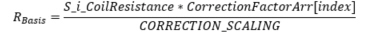
, where
CorrectionFactorArr[index] is the correction factor from array defined in application,
index = S_i_CurrentRequest / S_i_ParStep, and
CORRECTION_SCALING = 1000
, RPI is the PI-controller
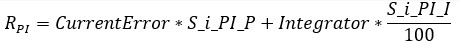
, where
CurrentError = OldCurrentRequest-i_MeasuredCurrent, and
Integrator = PI-controller integrator term
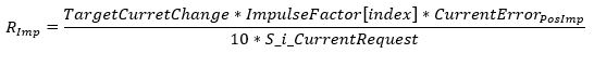
, RImp is the startup impulse
Positive direction
Negative direction

, where
TargetCurrentChange = S_i_CurrentRequest-OldCurrentRequest,
ImpulseFactor[Index] = Impulse up/down factor from array defined in application,
CurrentErrorPosImp = S_i_CurrentRequest-i_CurrentMeasured and
CurrentErrorNegImp = i_CurrentMeasured-S_i_CurrentRequest
, Feedforward term RFF

, where fffactor= 0.018
PWM Ratio Calculation SP19PWM Ratio Calculation SP19
The output PWM ratio o_PWMRatio is calculated from equation 1 (Ohm’s law)

,where RBasis is the base value for resistance
, where
CorrectionFactorArr[index] is the correction factor from array defined in application,
index = S_i_CurrentRequest / S_i_ParStep, and
CORRECTION_SCALING = 1000
, RPI is the PI-controller
, where
CurrentError = OldCurrentRequest-i_MeasuredCurrent, and
Integrator = PI-controller integrator term
, RImp is the startup impulse
Positive direction
Negative direction
, where
TargetCurrentChange = S_i_CurrentRequest-OldCurrentRequest,
ImpulseFactor[Index] = Impulse up/down factor from array defined in application,
CurrentErrorPosImp = S_i_CurrentRequest-i_CurrentMeasured and
CurrentErrorNegImp = i_CurrentMeasured-S_i_CurrentRequest
The following figure includes the current request, measured current and PWM ratio as a function of time.
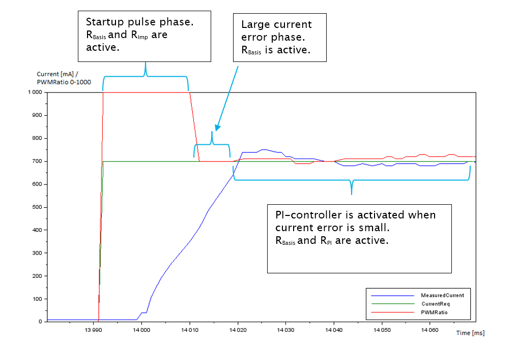
The function block includes a startup impulse feature for faster achievement of the target current. The startup impulse has two different modes: automatic and manual mode. Depending on the selected mode, PWM output is momentarily bigger until either the given time is exceeded (manual mode) or the measured current rises enough (automatic mode). The used mode is defined by an input S_i_AutomaticStartImpulse.
Manual mode:
In manual mode the input parameter S_i_StartImpulseTime defines the startup pulse length.
Automatic mode:
In automatic mode the startup pulse is stopped when the measured current is increased enough.
-
-
If the current request changes from 0 mA to some current (more than S_i_ParStep) then the measured current needs to be half (library internal constant) of the target current until the pulse is stopped. In figure in Operation section, the request current changes from 0 mA to 700 mA so the measured current needs to be 350 mA until the pulse is stopped.
-
If the current request changes from positive current to some other bigger current (more than S_i_ParStep) then the measured current needs to increase 1/8 (library internal constant) from the difference of the new current request and the measured current in start point.
The
PI controller is activated when current error is small (≤ S_i_ParStep/2) or if the target current is
not reached fast enough.
The input parameter
S_i_CurrentChangeSpeed [mA/ms]
defines how quick the measured current should change.
For example,
The PI controller
is deactivated when a new start-up pulse is started.
The
output o_PWMRatio is set
to 0 and o_Status.OutputValid
are set false, corresponding error bit is set in o_Status
and corresponding EventID
value is set to EventCode
if:
-
S_i_CurrentRequest >
5000 OR
-
S_i_SupplyVoltMeasured
≤ 0 OR
-
Output
wire broken or overcurrent situation detected OR
-
The
input parameters are invalid
The output
wire broken situation is detected when current request is active (S_i_WireBrokenLimit ≤ S_i_CurrentRequest)
and the measured current is below S_i_WireBrokenLimit
over diagnostic delay time S_i_DiagnosticDelay.
The overcurrent
situation is detected when the measured current is above S_i_OverCurrentLimit
during diagnostic delay time S_i_DiagnosticDelay.
The output
o_PWMRatio is set to 0, o_Status.OutputValid is set to
false immediately if:
If the PI-controller
integrator term error is detected the output o_Status.PI_I_TermError
is set true but otherwise
control is continued normally. In this case EventCode is not activated.
The o_Status
error bits and EventCode
error are not reset before the rising edge of i_Enable
input.
For accurate parameter adjusting it is recommended to utilize some CAN bus diagnostic tool, which gives the possibility to graphically monitor CAN signals. The monitored signals are
-
- S_i_CurrentRequest,
- i_CurrentMeasured and
- o_PWMRatio
These signals should be transmitted to CAN bus as short transmission period as possible (for example,10 ms) to get a good understanding how the different parameters affect to o_PWMRatio and i_CurrentMeasured.
The examples in following sections assumes that
-
-
S_i_ParameterCount = 20
-
S_i_ParStep = 50
-
meaning that the first index value in arrays corresponds the current value 50 mA, the second value corresponds the current value 100 mA, ..., the last index value corresponds the current value 1000 mA
Rough instructions for adjusting PI controller's P and I terms:
-
Set inputs S_i_PI_I and S_i_PI_P to value 1
-
Increase S_i_PI_P value (and test with different current requests) until current starts to oscillate. After that decrease S_i_PI_P value a few digits
-
Increase S_i_PI_I value (and test with different current requests) until current starts to oscillate. After that decrease S_i_PI_I value a few digits
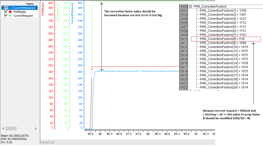
The correction parameters i_pCorrectionParameters are used to calculate the basis value to o_PWMRatio. The idea is that with correction parameters the o_PWMRatio value is set immediately close to the "correct" value and the PI controller is only used to fix the minor residual current error.
The following example graph shows how to adjust the correction factor value to correspond to the current request 400 mA.
-
-
Set S_i_PI_P = 0 and S_i_PI_I = 0 in order PI controller is not activated
-
Set S_i_UseImpulse = FALSE in order start impulse is not in use
-
Set S_i_CurrentRequest = 400 mA
-
Analyze graph to decide if correction factor value should be modified
|
|
In many applications it is enough adjust just the correction parameter which corresponds the minimum current and copy that value to all indexes in correction parameter array.
|
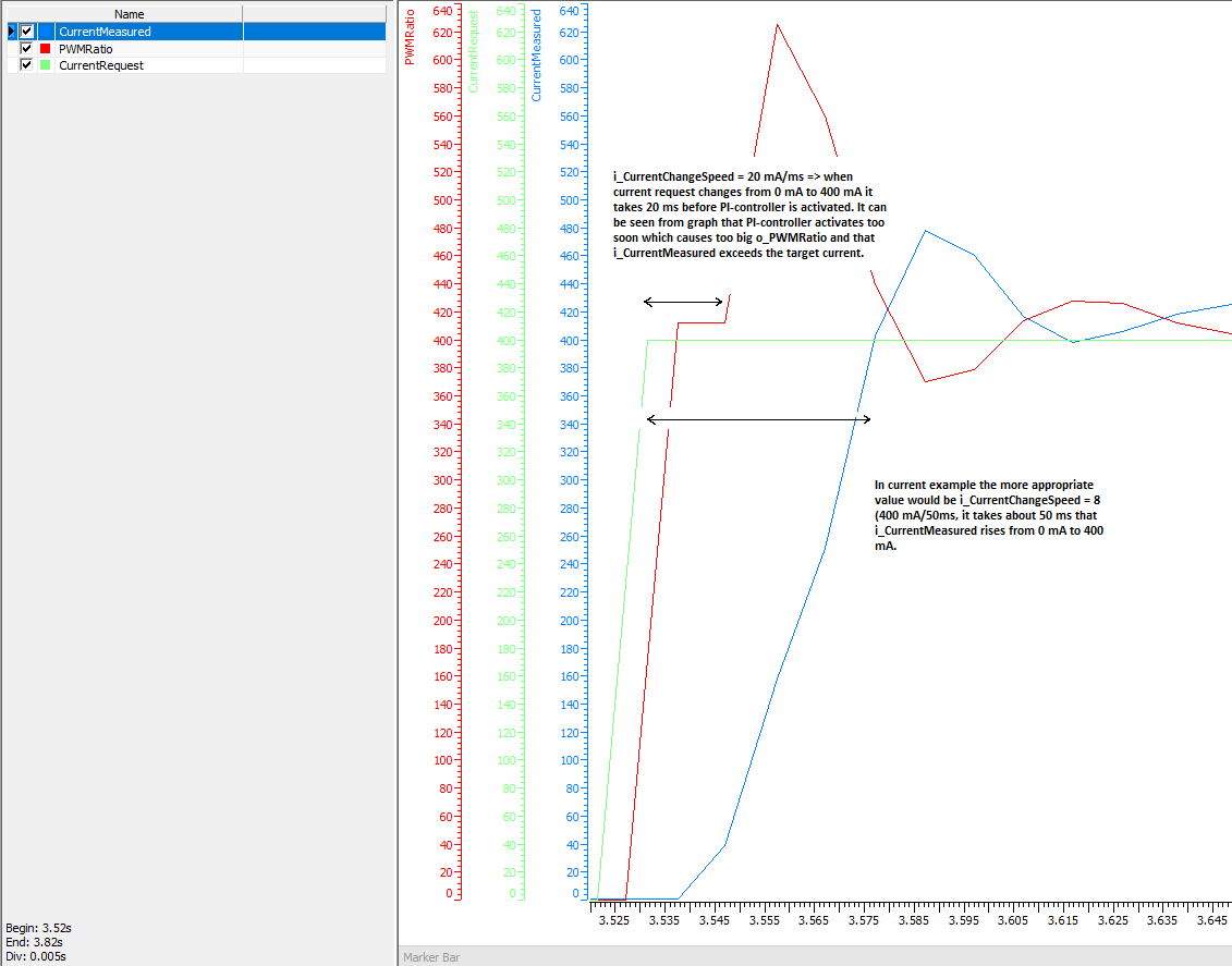
The input S_i_CurrentChangeSpeed is used to define the time delay before PI controller is activated. S_i_CurrentChangeSpeed affects always when the change of S_i_CurrentRequest is more than S_i_ParStep between two consecutive S_AdaptiveController function block instance calls. Typically this situation occurs only in the beginning of movement when current request changes from 0 mA to minimum current.
The following graph shows how to adjust the current change speed. The current request S_i_CurrentRequest changes from 0 mA to 400 mA.
S_i_CurrentChangeSpeed value 20 mA/ms is too big which causes that PI controller is activated too quickly.
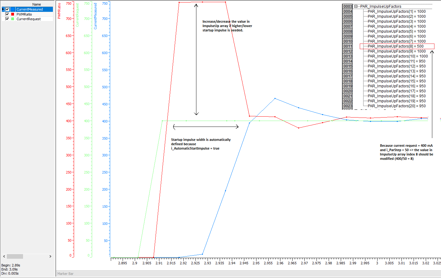
The input i_pImpulseUpParameters
is used to define the startup impulse to o_PWMRatio
which will cause that current increases more quickly. i_pImpulseUpParameters
affects always when the change of S_i_CurrentRequest
is more than S_i_ParStep between
two consecutive S_AdaptiveController
function block instance calls. Typically this situation occurs only
in the beginning of movement when current request changes from 0 mA
to minimum current. Note that S_i_UseImpulse
needs to be true that startup impulse is used.
The following graph shows how to adjust
impulse up parameters. S_i_CurrentRequest
changes from 0 mA to 400 mA.
|
|
In
many applications it is enough adjust just the impulse up
parameter which corresponds the minimum current and the rest
of indexes in impulse up parameter array can be ignored.
|
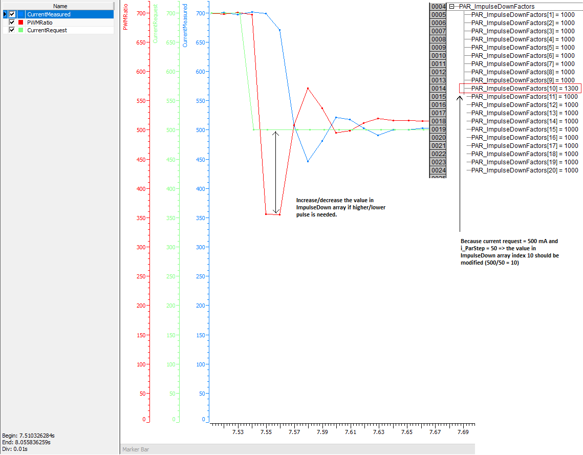
The input i_pImpulseDownParameters
is used to define the downward impulse to o_PWMRatio
which will cause that current decreases more quickly. i_pImpulseDownParameters
affects always when the change (decrease) of i_CurrentRequest
is more than i_ParStep between
2 consecutive PVC_AdaptiveController
FB instance calls. In many typical applications this do not occur
ever so impulse down parameters can be ignored. Note that i_UseImpulse
needs to be true that downward impulse is used.
The following graph shows how to adjust
impulse down parameters. S_i_CurrentRequest
changes from 700 mA to 500 mA.
|
|
In
many applications the values in impulse down parameter array
can be ignored. However, the impulse down array needs always
to be defined and given to the PVC_AdaptiveController
as a input.
|
|
|
Parameter automatic learning (S_i_LearnOn) is not supported.
|
|
Input variable name
|
Data type
|
Unit
|
Range
|
Description
|
|
i_Enable
|
BOOL
|
-
|
-
|
Enable POU operation.
|
|
S_i_CurrentRequest
|
SAFEUINT
|
mA
|
0 - 5000
|
Requested current value.
|
|
i_CurrentMeasured
|
DWORD
|
mA
|
0 - S_i_OverCurrentLimit
|
Measured current value.
|
|
S_i_SupplyVoltMeasured
|
SAFEDINT
|
mV
|
> 0
|
Measured supply voltage.
|
|
Input variable name
|
Data type
|
Unit
|
Range
|
Description
|
|
i_Enable
|
BOOL
|
-
|
-
|
Enable POU operation.
|
|
S_i_CurrentRequest
|
SAFEUINT
|
mA
|
0 - 5000
|
Requested current value.
|
|
i_CurrentMeasured
|
DINT
|
mA
|
0 - S_i_OverCurrentLimit
|
Measured current value.
|
|
S_i_SupplyVoltMeasured
|
SAFEDINT
|
mV
|
> 0
|
Measured supply voltage.
|
Outputs
|
Output variable name
|
Data type
|
Range
|
Description
|
|
o_PWMRatio
|
DWORD
|
0 - G_PWM_OUT_MAX_VALUE
|
Control value to PWM output.
|
|
o_Status
|
Status
|
-
|
Status of output value. See Status structure.
|
Error diagnostic
See Diagnostic Interface library description of error status and event code functionality.
|
Conditions
|
o_PWMRatio
|
o_Status. OutputValid
|
o_Status error status
|
Event code FunctionID
|
Event code EventID
|
Description
|
|
i_Enable TRUE AND
init parameter error AND
i_pEventCode valid
|
0
|
FALSE
|
ParameterError
|
CURRENT
CONTROLLER
|
PARAMETER_ERROR
|
Check initialization parameters
|
|
i_Enable TRUE AND
init parameter error AND
i_pEventCode NULL
|
0
|
FALSE
|
ParameterError
|
-
|
-
|
Add event code
|
|
i_Enable rises AND
init parameters ok AND
signal voltage within given limits
|
PWM ratio
|
TRUE
|
-
|
NO_FUNC
|
NO_ERROR
|
Normal operation
|
|
i_Enable TRUE AND
init parameters ok AND
S_i_CurrentRequest > 5000
|
0
|
FALSE
|
InputHigh
|
CURRENT
CONTROLLER
|
INPUT_TOO_HIGH
|
Check current request level
|
|
i_Enable TRUE AND
init parameters ok AND
S_i_SupplyVoltMeasured ≤ 0
|
0
|
FALSE
|
InputLow
|
CURRENT
CONTROLLER
|
INPUT_TOO_LOW
|
Check supply voltage level. Also check that outputs are energized when calling the function block.
|
|
i_Enable TRUE AND
init parameters ok AND
i_CurrentMeasured > S_i_OverCurrentLimit
|
0
|
FALSE
|
OverCurrentError
|
CURRENT
CONTROLLER
|
OVER_CURRENT
|
Check wires
|
|
i_Enable TRUE AND
init parameters ok AND S_i_CurrentRequest > 0 AND i_CurrentMeasured < S_i_WireBrokenLimit
|
0
|
FALSE
|
WireBrokenError
|
CURRENT
CONTROLLER
|
WIRE_BROKEN
|
Check wires
|
|
i_Enable TRUE AND
init parameters ok AND PI controller internal integrator (I) term out of limits (range -500000...500000)
|
PWM ratio
|
TRUE
|
PI_I_TermError
|
NO_FUNC
|
NO_ERROR
|
The requested current is never reached. Check
- requested current
- P and I terms
Typically, this error occurs if S_i_CurrentRequest is too high
Note that the input S_i_DiagnosticDelay does not affect this error.
|
Default values for different valve types
Parker valve 22 Ω
(*Parker valve default values to code*)
(*Correction factors*)
(*50 100 150 200 250 300 350 400 450 500 550 600 650 700 750 800 850 900 950 1000 mA*)
ccParams:ARRAY [1..20] OF UINT := [ 1359,1307,1231,1172,1137,1113,1103,1093,1088,1076,1075,1075,1075,1078,1076,1075,1034,1014,1014,1014];
(*Impulse up factors*)
(*50 100 150 200 250 300 350 400 450 500 550 600 650 700 750 800 850 900 950 1000 mA*)
ccParamsImpUp: ARRAY [1..20] OF UINT := [ 1000,1000,1000,1000,1000,1000,1000,1000,1000,1000,950,950,950,950,950,950,950,950,950,950];
(*Impulse down factors*)
(*50 100 150 200 250 300 350 400 450 500 550 600 650 700 750 800 850 900 950 1000 mA*)
ccParamsImpDown:ARRAY [1..20] OF UINT:= [ 1200,1200,1100,1000,1000,1000,1000,1000,1000,1000,1000,1000,1000,1000,1000,1000,1000,1000,1000,1000];
Hydraforce 29 Ω
(*Correction factors*)
(*50 100 150 200 250 300 350 400 450 500 550 600 650 700 750 800 mA*)
ccParams:ARRAY [1..16] OF UINT := [ 1230,1230,1190,1080,1070,1010,1010,1010,1010,1010,1010,1010,1010,1010,1010,1010];
(*Impulse up factors*)
(*50 100 150 200 250 300 350 400 450 500 550 600 650 700 750 800 mA*)
ccParamsImpUp: ARRAY [1..16] OF UINT := [ 1000,1000,1000, 950, 950,950,950,950, 950,950, 950,950,950,950,950, 950];
(*Impulse down factors*)
(*50 100 150 200 250 300 350 400 450 500 550 600 650 700 750 800 mA*)
ccParamsImpDown:ARRAY [1..16] OF UINT:= [ 1200,1200,1100,1000,1000,1000,1000,1000,1000,1000,1000,1000,1000,1000,1000,1000];
How to use S_AdaptiveController as traditional PI-controller
It is possible to use S_AdaptiveContoller as traditional PI-controller by using the following settings:
-
Call AdvancedInit method once with the following input values
-
Set every index of Correction parameters array (Init method input i_pCorrectionParameters address to this array) to value 1.
See also
Source file topic100403.htm
Last updated 4-Sep-2025