Supported platforms: CODESYS 3.5 SAFETY, CODESYS 3.5 SP19 SAFETY
This section describes how to review generated code related to I/O.
A MultiTool Creator project defines variable names for all user defined I/O.
In a safety control unit, user shall also define which I/O is safety related. This is done in MultiTool Creator using I/O > Safety related setting.
Safety related setting affects the context I/O is mapped to.
Mapped I/O variables depend on the used pin type and the used mode. See hardware specific I/O Programming sections.
For example, Programming > Programming SC52 Safety Control Unit > I/O Programming.
IO_interface is a component generated in CODESYS, directly under the device.
Check each used I/O pin. The IO_interface > IO_interface I/O mapping tab has a folder for each I/O pin.
Verify that all I/O pins which are selected to be used in MultiTool Creator have mapped variables
Verify that the mapped variable name matches with name given in MultiTool Creator (see the example image in step 2)
Verify that all relevant variables are mapped for the selected I/O mode (See hardware specific I/O programming)
Check the pin context. The variable is mapped to a different code template program depending on MultiTool Creator's Safety related setting
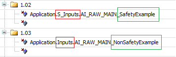
Verify that all safety related inputs are mapped to the S_Inputs program
Verify that all safety related outputs are mapped to the S_Outputs program
Verify that all non-safety related inputs are mapped to the Inputs program
Verify that all non-safety related outputs are mapped to the Outputs program
The following image highlights the program name in red and the variable name in green, defined in MultiTool Creator.
Check internal diagnostic mapping. Verify that all I/O variables under the Internal or Diagnostic folder are mapped to the S_Inputs program. These are used by hardware diagnostics.
All I/O initialization code (safety & non-safety related) is added to the S_Init_IO program.
Verify that the program is executed from S_PLC_PRG.
|
S_PLC_PRG Code: |
|
IF NOT o_InitDone AND PLC_PRG.o_InitDone THEN (* Code template safe FB initializations *) IF NOT S_Init_IO.o_Ready THEN S_Init_IO(); |
Verify initialization code generated to S_Init_IO program.
I/O initialization code does not depend on Safety related selection in MultiTool Creator
I/O initialization does depend on the used pin type, mode and configurations (selected in MultiTool Creator)
See hardware specific I/O programming sections for required initializations in each pin type/mode
|
|
Pin and connector numbers are added to I/O initialization for diagnostic purposes when using MultiTool 6.4 (SDK3.6) or later, or MultiTool Creator. |
The following variable definitions are added to the S_Init_IO program.
|
S_Init_IO Definitions |
|
PROGRAM S_Init_IO VAR_INPUT END_VAR VAR_OUTPUT o_Ready: SAFEBOOL := FALSE; o_Error: BOOL := FALSE; o_ErrorInConnector: DWORD := DWORD#0; o_ErrorInPin: DWORD := DWORD#0; o_FWErrorCode: EPEC_SYSTEM.SYSTEM_ERROR_CODES; END_VAR VAR result: EPEC_SYSTEM.SYSTEM_ERROR_CODES;
pin: DWORD := DWORD#0; connector: DWORD := DWORD#0; info1: DWORD := DWORD#0; // MSW connector, LSW pin info2: DWORD := DWORD#0; // error specific END_VAR |
I/O initialization code always begins by setting the I/O driver to IODRV_STATE_CONFIGURATION:
|
S_Init_IO Code |
|
IF result = EPEC_SYSTEM.SYSTEM_ERROR_CODES.FW_ERR_OK THEN result := EPEC_IODRV.IoDrvSetState(EPEC_IODRV.IoDrvStates.IODRV_STATE_CONFIGURATION); END_IF |
After I/O driver is set to configuration mode the following is generated:
All I/O pin related initializations
Internal diagnostic initializations
Firmware error is checked at each initialization function.
|
|
When I/O init's output o_Error is TRUE following diagnostic can be used by application:
|
|
|
Error code is added to application log only when device description includes SafeErrorLog library. In SC52 device description 3.5.10.6 or later is required. See also How to use application error log. |
I/O initialization code always ends with error checking and setting the I/O driver to IODRV_STATE_RUN:
|
S_Init_IO Code |
|
IF result = EPEC_SYSTEM.SYSTEM_ERROR_CODES.FW_ERR_OK THEN result := EPEC_IODRV.IoDrvSetState(EPEC_IODRV.IoDrvStates.IODRV_STATE_RUN); o_FWErrorCode := result; END_IF IF result <> EPEC_SYSTEM.SYSTEM_ERROR_CODES.FW_ERR_OK THEN o_Error:=TRUE; o_ErrorInConnector := connector; o_ErrorInPin := pin; o_FWErrorCode := result;
info1 := SHL(connector, 16) OR pin; EPEC_SERRLOG.S_AddError_DWORD( i_ErrorCode := ApplicationErrors.IO_INIT, i_LibraryErrorCode := result, i_Info1 := info1, // MSW connector, LSW pin i_Info2 := info2 // error specific ); END_IF
o_Ready:=TRUE; |
Verify that the S_Inputs program is called from S_PLC_PRG.
Initialization phase:
|
S_PLC_PRG Code: |
|
ELSIF NOT S_Inputs.o_InitReady THEN S_Inputs(i_Initialize:=TRUE); |
Run phase:
|
S_PLC_PRG Code: |
|
ELSIF PLC_PRG.o_Initdone THEN (* Safe actions to execute before safe main program *) S_Inputs(i_Initialize:=FALSE); (* ... *) S_Main(); |
If the project has non-safety related inputs, verify that the Inputs program is called from PLC_PRG.
Initialization phase:
|
PLC_PRG Code: |
|
|
ELSIF NOT Inputs.o_InitReady THEN Inputs(i_Initialize:=TRUE); |
|
Run phase:
|
PLC_PRG Code: |
|
|
ELSIF S_PLC_PRG.o_InitDone THEN (* ... *) Inputs(i_Initialize:=FALSE); (* ... *) Main(); |
|
Verify the generated code for safety related inputs
Same variables are generated regardless of Safety related selection in MultiTool Creator.
AI / DI measurement variables in S_Inputs are generated using SAFEDINT / SAFEBOOL type instead of DINT and BOOL.
|
|
There are no function blocks generated for pulse inputs. For PI mode, the code template only assigns io-interface mapped variable values to the S_Inputs / Inputs PRG interface. |
|
|
SafeConversion library version 1.0.1.2
SafeConversion library version 1.1.0.0 or later
|
The following table lists the function blocks and functions which are generated for inputs depending on the mode:
|
Name |
Input mode |
Description |
|
S_ADCToVoltageOrCurrent |
AI V TI |
Raw ADC to SI value conversion - With Cat. 2 mode there is two AD conversions for main and redundant channel. - With AI V mode there is also pull-up voltage measurement on pins that have pull-up measurement available and pull-up is enabled - With TI mode there is always main AI and pull-up voltage measurement - In DI mode only for AI/DI pin types which have voltage measurement |
|
S_VoltageToDI |
DI |
Voltage to DI conversion (with debounce filtering, SafeConversion 1.0.1.2) |
|
S_DebounceDI (SafeConversion 1.1.0.0 or later) |
DI |
DI debounce filtering |
|
S_AIOverCurrentProtection |
AI mA |
Over current monitoring for mA measurements |
|
S_VoltageToResistance |
TI |
Voltage to resistance conversion |
|
S_AddError_BYTE |
AI V TI |
Adds input errors to application log. Generated only when using device description with SafeErrorLog available. |
MultiTool 6.6 or older code template uses constant limits for AI measurements.
S_ADCToVoltageOrCurrentS_ADCToVoltageOrCurrent
Verify that the function block instance is generated for each relevant pin
Cat. 2 mode has a second instance for redundant measurement
Type 096 pin (or other type with pull-up) has an instance for pull-up measurement
Verify that the Init method is executed for each instance
Output maximum: According to hardware specific enumeration for each pin type
Output high limit (AI V or AI mA mode): Hardware specific constants according to measurement range (e.g. 5V high voltage, 10V high voltage or high current)
Output high limit (DI mode): Same as output maximum
Cat2MonitoringCh input is FALSE in all other cases except in Cat. 2 redundant channel's AD conversion
Diagnostic delay: Hardware specific constant
Verify that the function block is executed for each instance
ADC raw value mapped to I/O interface is set in i_ADCValue
Corresponding output variable is updated with S_o_Output
The following is an initialization example of type 091 pin Joystick_Y_B in AI V mode using 10V range
|
Initialization: |
|
o_InitReady := o_InitReady AND FBScaleToSIUnits_Joystick_Y_B.Init( S_i_OutputMaximum := EPEC_HW.VALUE_AT_AD_MAXIMUM.U_TYPE091_10V, S_i_OutputHighLimit := EPEC_HW.Constants.G_AI_10V_HIGH_VOLTAGE , S_i_OutputLowLimit := EPEC_HW.Constants.G_AI_LOW_VOLTAGE, S_i_Cat2MonitoringCh := FALSE, S_i_DiagnosticDelay := EPEC_HW.Constants.G_VOLTAGE_INPUT_DIAGNOSTIC_DELAY, i_pEventCode := ADR(o_EventCode_Joystick_Y_B)); |
The following is an initialization example of type 093 pin Joystick_X_PosSwitch in DI mode
|
Initialization: |
|
o_InitReady := o_InitReady AND FBScaleToSIUnits_Joystick_X_PosSwitch.Init( S_i_OutputMaximum := EPEC_HW.VALUE_AT_AD_MAXIMUM.U_TYPE093_10V, S_i_OutputHighLimit := EPEC_HW.VALUE_AT_AD_MAXIMUM.U_TYPE093_10V , S_i_OutputLowLimit := DINT#0, S_i_Cat2MonitoringCh := FALSE, S_i_DiagnosticDelay := EPEC_HW.Constants.G_VOLTAGE_INPUT_DIAGNOSTIC_DELAY, i_pEventCode := ADR(o_EventCode_Joystick_X_PosSwitch)); |
The following is an initialization example of type 093 pin Position in Cat. 2 mode. If AI mA mode is used, then redundant channel is not used.
|
Initialization: |
|
o_InitReady := o_InitReady AND FBScaleToSIUnits_Position.Init( S_i_OutputMaximum := EPEC_HW.VALUE_AT_AD_MAXIMUM.I_TYPE093_20mA, S_i_OutputHighLimit := EPEC_HW.Constants.G_AI_HIGH_CURRENT , S_i_OutputLowLimit := EPEC_HW.Constants.G_AI_LOW_CURRENT, S_i_Cat2MonitoringCh := FALSE, S_i_DiagnosticDelay := EPEC_HW.Constants.G_CURRENT_INPUT_DIAGNOSTIC_DELAY, i_pEventCode := ADR(o_EventCode_Position));
o_InitReady := o_InitReady AND FBScaleToSIUnitsCat2Redundant_Position.Init( S_i_OutputMaximum := EPEC_HW.VALUE_AT_AD_MAXIMUM.I_TYPE093_20mA, S_i_OutputHighLimit := EPEC_HW.Constants.G_AI_HIGH_CURRENT , S_i_OutputLowLimit := EPEC_HW.Constants.G_AI_LOW_CURRENT, S_i_Cat2MonitoringCh := TRUE, S_i_DiagnosticDelay := EPEC_HW.Constants.G_CURRENT_INPUT_DIAGNOSTIC_DELAY, i_pEventCode := ADR(o_EventCode_Position)); |
The following is a run phase code example of AD conversion. The same principle applies to AI V, AI mA, Cat. 2 and DI. Variable prefixes may differ depending on measurement.
|
Code: |
|
FBScaleToSIUnits_Joystick_Y_B ( i_Enable := i_Enable, i_ADCValue := AI_RAW_MAIN_Joystick_Y_B, (*Variable mapped to I/O interface*) o_Status => o_AiScaleStatus_Joystick_Y_B, S_o_Output => o_AI_MAIN_Joystick_Y_B); (*Variable used by application*) |
MultiTool 6.7 or newer code template uses user defined limits for AI measurements.
S_ADCToVoltageOrCurrentS_ADCToVoltageOrCurrent
Verify that the function block instance is generated for each relevant pin
Cat. 2 mode has a second instance for redundant measurement
Instance for pull-up measurement is generated for
AI V pins with pull-up measurement available (e.g. type 096) when configurable pull-up is enabled
In TI mode pull-up measurement is always generated
Verify that the Init method is executed for each instance
Output maximum: According to hardware specific enumeration for each pin type
Output low and high limit (AI V, AI mA or TI mode): User defined limit from MultiTool is used for main AI channel
Output high limit (DI mode): Same as output maximum
Cat2MonitoringCh input is FALSE in all other cases except in Cat. 2 redundant channel's AD conversion
Diagnostic delay: Hardware specific constant
Verify that the function block is executed for each instance
Check that i_ADCValue input is assigned
AI V, TI and DI modes: ADC raw value mapped to I/O interface is set in i_ADCValue
AI mA and Cat. 2 modes:
SafeSSeriesHardware up to version 1.3.2.7:
ADC raw value mapped to I/O interface is set in i_ADCValue
SafeSSeriesHardware version 1.4.0.0 and newer:
ADC value from overcurrent protection block's output is used for AI main channel
ADC raw value mapped to I/O interface is used for Cat. 2 redundant channel
Corresponding output variable is updated with S_o_Output
The following is an initialization example of type 091 pin Joystick_Y_B in AI V mode using 10V range
|
Initialization: |
|
o_InitReady := o_InitReady AND FBScaleToSIUnits_Joystick_Y_B.Init( S_i_OutputMaximum := EPEC_HW.VALUE_AT_AD_MAXIMUM.U_TYPE091_10V, S_i_OutputHighLimit := 10000, S_i_OutputLowLimit := 0, S_i_Cat2MonitoringCh := FALSE, S_i_DiagnosticDelay := EPEC_HW.Constants.G_VOLTAGE_INPUT_DIAGNOSTIC_DELAY, i_pEventCode := ADR(o_EventCode_Joystick_Y_B)); |
The following is an initialization example of type 093 pin Joystick_X_PosSwitch in DI mode
|
Initialization: |
|
o_InitReady := o_InitReady AND FBScaleToSIUnits_Joystick_X_PosSwitch.Init( S_i_OutputMaximum := EPEC_HW.VALUE_AT_AD_MAXIMUM.U_TYPE093_10V, S_i_OutputHighLimit := EPEC_HW.VALUE_AT_AD_MAXIMUM.U_TYPE093_10V , S_i_OutputLowLimit := DINT#0, S_i_Cat2MonitoringCh := FALSE, S_i_DiagnosticDelay := EPEC_HW.Constants.G_VOLTAGE_INPUT_DIAGNOSTIC_DELAY, i_pEventCode := ADR(o_EventCode_Joystick_X_PosSwitch)); |
The following is an initialization example of type 093 pin Position in Cat. 2 mode.
If AI mA mode is used, then redundant channel is not generated.
|
Initialization: |
|
o_InitReady := o_InitReady AND FBScaleToSIUnits_Position.Init( S_i_OutputMaximum := EPEC_HW.VALUE_AT_AD_MAXIMUM.I_TYPE093_20mA, S_i_OutputHighLimit := 21900 , S_i_OutputLowLimit := 0, S_i_Cat2MonitoringCh := FALSE, S_i_DiagnosticDelay := EPEC_HW.Constants.G_CURRENT_INPUT_DIAGNOSTIC_DELAY, i_pEventCode := ADR(o_EventCode_Position));
o_InitReady := o_InitReady AND FBScaleToSIUnitsCat2Redundant_Position.Init( S_i_OutputMaximum := EPEC_HW.VALUE_AT_AD_MAXIMUM.I_TYPE093_20mA, S_i_OutputHighLimit := 21900 , S_i_OutputLowLimit := 0, S_i_Cat2MonitoringCh := TRUE, S_i_DiagnosticDelay := EPEC_HW.Constants.G_CURRENT_INPUT_DIAGNOSTIC_DELAY, i_pEventCode := ADR(o_EventCode_Position)); |
The following is an initialization example of TemperatureSensor in TI mode
The output maximum for pull-up measurement depends on used resistance range. The resistance range defines if GAIN is set OFF/ON which affects the output maximum scaling.
See control unit specific I/O programming topic for I/O init examples
|
Initialization: |
|
o_InitReady := o_InitReady AND FBScaleToSIUnitsMain_TemperatureSensor.Init( (*...*) o_InitReady := o_InitReady AND FBScaleToSIUnitsPullup_TemperatureSensor.Init( |
The following is a run phase code example of AD conversion.
Variable prefixes may differ depending on measurement.
Example applies to:
AI V mode
DI mode
AI mA with SafeSSeriesHardware up to version 1.3.2.7
Cat. 2 mode with SafeSSeriesHardware up to version 1.3.2.7 (note that Cat. 2 mode has main and redundant measurements)
|
|
AI mA & Cat. 2 modes: Runtime code is executed before S_AIOverCurrentProtection. |
|
Code: |
|
FBScaleToSIUnits_Joystick_Y_B ( i_Enable := i_Enable, i_ADCValue := AI_RAW_MAIN_Joystick_Y_B, (*Variable mapped to I/O interface*) o_Status => o_AiScaleStatus_Joystick_Y_B, S_o_Output => o_AI_MAIN_Joystick_Y_B); (*Variable used by application*) |
The i_Enable line is generated in following way if product supports pin specific enable variables:
|
Code: |
|
i_Enable := i_Enable AND i_Enable_Joystick_Y_B, |
The following is a run phase code example of AD conversion for AI mA mode with SafeSSeriesHardware version 1.4.0.0 or newer.
|
|
Runtime code is executed after S_AIOverCurrentProtection. |
|
Code: |
|
FBScaleToSIUnits_Position ( i_Enable := o_AiOverCurrentStatus_Position.OutputValid, i_ADCValue := FbOvercurrent_Position.o_ADCValue, o_Status => o_AiScaleStatus_Position, S_o_Output => o_AI_MAIN_Position); |
The following is a run phase code example of AD conversion for Cat.
2 mode with SafeSSeriesHardware
version 1.4.0.0 or newer.
|
|
Runtime code is executed after S_AIOverCurrentProtection. |
|
Code: |
|
FBScaleToSIUnits_Position ( i_Enable := o_AiOverCurrentStatus_Position.OutputValid, i_ADCValue := FbOvercurrent_Position.o_ADCValue, o_Status => o_AiScaleStatus_Position, S_o_Output => o_AI_MAIN_Position);
FBScaleToSIUnitsCat2Redundant_Position ( i_Enable := o_AiOverCurrentStatus_Position.OutputValid, i_ADCValue := AI_RAW_MAIN_REDUNANT_Position, o_Status => o_AiScaleStatusRedundant_Position, S_o_Output => o_AI_REDUNDANT_Position); |
The following is a run phase code example of AD conversion for TI mode
|
Code: |
|
(* Scale raw value and set it to output variable *) (* Scale raw value and set it to output variable *) |
The following example applies to products which support TI mode (e.g. SL8X1-01).
S_VoltageToResistanceS_VoltageToResistance
Verify that the function block instance is generated for each relevant pin
Verify that the Init method is executed for each instance
Internal pullup resistance: Depends on used resistance range
The selected resistance range affects the selected pullup mode
See control unit specific I/O programming topic for I/O init examples
Output resistance low and high limit: User defined limit from MultiTool
Diagnostic delay: Hardware specific constant
Verify that the function block is executed for each instance
Check that S_i_Voltage input is assigned: Measured voltage from AD conversion
Check that S_i_RefVoltage input is assigned: Measured pullup voltage from pullup AD conversion
Corresponding output variable is updated with S_o_Resistance
The following is an initialization example
|
Initialization: |
|
o_InitReady := o_InitReady AND FBScaleToResistance_TemperatureSensor.Init( |
The following is a run phase code example
|
Code: |
|
FBScaleToResistance_TemperatureSensor (i_Enable := i_Enable AND i_Enable_TemperatureSensor, |
The following example applies with SafeConversion version 1.0.1.2:
Verify that function block instance is generated for each DI
Verify that Init method is executed for each instance
Threshold high & low are set according to values set in MultiTool
Debounce delay is set according to value set in MultiTool
Verify that function block is executed for each instance
AD conversion's output valid flag is used as enable condition
S_i_Voltage input to DI filtering is set according to AD conversion's S_o_Output.
Corresponding DI state is updated with S_o_DigitalState
The following is an initialization example of DI filtering for Joystick_X_PosSwitch
|
Initialization: |
|
o_InitReady := o_InitReady AND FBVoltagetoDi_Joystick_X_PosSwitch.Init( S_i_ThresholdHigh := 4500, (*Value from MultiTool*) S_i_ThresholdLow := 3500, (*Value from MultiTool*) S_i_DebounceDelay := 30, (*Value from MultiTool*) i_pEventCode := ADR(o_EventCode_Joystick_X_PosSwitch)); |
The following is a run phase code example of DI filtering for Joystick_X_PosSwitch
|
Code: |
|
FBVoltagetoDi_Joystick_X_PosSwitch( i_Enable := FBScaleToSIUnits_Joystick_X_PosSwitch.o_Status.OutputValid, S_i_Voltage := FBScaleToSIUnits_Joystick_X_PosSwitch.S_o_Output, o_Status => o_DiConversionStatus_Joystick_X_PosSwitch, S_o_DigitalState => o_DI_Joystick_X_PosSwitch); |
The following examples apply with SafeConversion version 1.1.0.0 or later:
DI filtering for AI/DI pin types
S_VoltageToDI & S_DebounceDIS_VoltageToDI & S_DebounceDI
Verify that function block instances are generated for each DI
Verify that Init method is executed for each S_VoltageToDI instance
Threshold high & low are set according to values set in MultiTool
Verify that Init method is executed for each S_DebounceDI instance
Debounce delay is set according to value set in MultiTool
Debounce type is set according to type set in MultiTool
Verify that function block is executed for each instance
AD conversion's output valid flag is used as enable condition
S_i_Voltage input to S_VoltageToDI is set according to AD conversion's S_o_Output.
S_i_DigitalState input to S_DebounceDI is set according to S_VoltageToDI's S_o_DigitalState
Corresponding DI state is updated with DI debounce's S_o_DigitalState
The following is an initialization example of DI filtering for Joystick_X_PosSwitch
|
Initialization: |
|
o_InitReady := o_InitReady AND FBVoltagetoDi_Joystick_X_PosSwitch.Init( S_i_ThresholdHigh := 4500, (*Value from MultiTool*) S_i_ThresholdLow := 3500, (*Value from MultiTool*) i_pEventCode := ADR(o_EventCode_Joystick_X_PosSwitch));
o_InitReady := o_InitReady AND FBDebounceDi_Joystick_X_PosSwitch.Init( S_i_DebounceDelay := 30, (*Value from MultiTool*) i_FilterType := EPEC_SC.DebounceFilterType.Debounce_Fast, (*Debounce type from MultiTool*) i_pEventCode := ADR(o_EventCode_Joystick_X_PosSwitch)); |
The following is a run phase code example of DI filtering for Joystick_X_PosSwitch
|
Code: |
|
FBVoltagetoDi_Joystick_X_PosSwitch( i_Enable := FBScaleToSIUnits_Joystick_X_PosSwitch.o_Status.OutputValid, S_i_Voltage := FBScaleToSIUnits_Joystick_X_PosSwitch.S_o_Output, o_Status => o_DiConversionStatus_Joystick_X_PosSwitch, S_o_DigitalState => );
FBDebounceDi_Joystick_X_PosSwitch( i_Enable := FBVoltagetoDi_Joystick_X_PosSwitch.o_Status.OutputValid, S_i_DigitalState := FBVoltagetoDi_Joystick_X_PosSwitch.S_o_DigitalState, o_Status => o_DiDebounceStatus_Joystick_X_PosSwitch, S_o_DigitalState => o_DI_Joystick_X_PosSwitch);
|
DI filtering for pin type without AI voltage measurement
Verify that function block instances are generated for each DI
Verify that Init method is executed for each S_DebounceDI instance
Debounce delay is set according to value set in MultiTool
Debounce type is set according to type set in MultiTool
Verify that function block is executed for each instance
S_i_DigitalState input is set according to pin's digital status
Corresponding DI state is updated with DI debounce's S_o_DigitalState
The following is an initialization example of DI filtering for Joystick_X_PosSwitch
|
Initialization: |
|
o_InitReady := o_InitReady AND FBDebounceDi_Joystick_X_PosSwitch.Init( S_i_DebounceDelay := 30, (*Value from MultiTool*) i_FilterType := EPEC_SC.DebounceFilterType.Debounce_Fast, (*Debounce type from MultiTool*) i_pEventCode := ADR(o_EventCode_Joystick_X_PosSwitch)); |
The following is a run phase code example of DI filtering for Joystick_X_PosSwitch
|
Code: |
|
FBDebounceDi_Joystick_X_PosSwitch( i_Enable := i_Enable, S_i_DigitalState := ST_Joystick_X_PosSwitch, o_Status => o_DiDebounceStatus_Joystick_X_PosSwitch, S_o_DigitalState
=> o_DI_Joystick_X_PosSwitch);
|
The i_Enable line is generated in following way if product supports pin specific enable variables:
|
Code: |
|
i_Enable := i_Enable AND i_Enable_Joystick_X_PosSwitch, |
The following examples apply for SafeSSeriesHardware 1.3.2.7 or older
S_AIOverCurrentProtectionS_AIOverCurrentProtection
Verify that the Init method is executed for each relevant pin
Verify that the function block is executed for each relevant pin
Measured current is set from AD conversion instance to S_i_Current input
In Cat. 2 mode, overcurrent protection is generated only for the main channel
The following is an initialization example of AI over current protection for Position
|
Initialization: |
|
o_InitReady := o_InitReady AND FbOvercurrent_Position.init(i_pEventCode := ADR(o_EventCode_Position)); |
The following is a run phase code example of AI overcurrent protection for Position
|
|
Runtime code is executed after S_ADCToVoltageOrCurrent. |
SC52 Safety Control Unit
|
Code: |
|
FbOvercurrent_Position( i_Enable := o_AiScaleStatus_Position.OutputValid AND o_AiScaleStatusRedundant_Position.OutputValid, S_i_Current:=o_AI_MAIN_Position, o_Status => o_AiOverCurrentStatus_Position); IF NOT o_AiOverCurrentStatus_Position.OutputValid AND i_Enable = TRUE THEN (* Over current error set pin to voltage mode *) EPEC_IODRV.IoDrvDOSetConfig (EPEC_HW.IO_Channels.PIN_1_02_DO_TYPE_V_mA, FALSE); END_IF |
SL84 Safety Control Unit
|
Code: |
|
FbOvercurrent_Position( i_Enable := o_AiScaleStatus_Position.OutputValid, S_i_Current:=o_AI_MAIN_Position, o_Status => o_AiOverCurrentStatus_Position); IF ((NOT o_AiOverCurrentStatus_Position.OutputValid) OR FBScaleToSIUnits_Position.o_Status.OutputHigh) AND i_Enable = TRUE THEN (* Over current error set pin to voltage mode *) EPEC_IODRV.IoDrvDOSetConfig (EPEC_HW.IO_Channels.PIN_1_1_DO_TYPE_V_mA, FALSE); END_IF |
The following examples apply for SafeSSeriesHardware 1.4.0.0 and newer
S_AIOverCurrentProtectionS_AIOverCurrentProtection
Verify that the Init method is executed for each relevant pin
Verify that the function block is executed for each relevant pin
ADC raw value mapped to I/O interface is set in i_ADCValue
In Cat. 2 mode, overcurrent protection is generated only for the main channel
The following is an initialization example of AI overcurrent protection for Position
|
Initialization: |
|
o_InitReady := o_InitReady AND FbOvercurrent_Position.init(i_pEventCode := ADR(o_EventCode_Position)); |
The following is a run phase code example of AI overcurrent protection for Position
|
|
Runtime code is executed before S_ADCToVoltageOrCurrent. |
|
Code: |
|
FbOvercurrent_Position( i_Enable := i_Enable, i_ADCValue := AI_RAW_MAIN_Position, o_Status => o_AiOverCurrentStatus_Position o_ADCValue => ); IF NOT o_AiOverCurrentStatus_Position.OutputValid AND i_Enable = TRUE THEN (* Over current error set pin to voltage mode *) EPEC_IODRV.IoDrvDOSetConfig (EPEC_HW.IO_Channels.PIN_1_02_DO_TYPE_V_mA, FALSE); END_IF |
The i_Enable line is generated in following way if product supports pin specific enable variables:
|
Code: |
|
i_Enable := i_Enable AND i_Enable_Position, |
The IF condition is generated in following way if product supports pin specific enable variables:
|
Code: |
|
IF NOT o_AiOverCurrentStatus_Position.OutputValid AND i_Enable AND i_Enable_Position THEN |
The following are examples of error log
S_AddError_BYTES_AddError_BYTE
Verify that the function is executed for each relevant input pin
|
|
Error code is added to application log only when device description includes SafeErrorLog library. In SC52 device description 3.5.10.6 or later is required. See also How to use application error log. |
The following is a run phase code example of adding pin X1_02 input error to application log
|
Code: |
|
EPEC_SERRLOG.S_AddError_BYTE( i_ErrorCode := ApplicationErrors.INPUTS, i_LibraryErrorCode := o_EventCode_X1_02.EventID, i_Info1 := o_EventCode_X1_02.FunctionID, i_Info2 := o_EventCode_X1_02.DeviceID, i_Info3 := o_EventCode_X1_02.ChannelID, i_Info4 := 1, // connector i_Info5 := 2, // pin i_Info6 := 0, i_Info7 := 0, i_Info8 := 0); |
If the project has safety related outputs, verify that the S_Outputs program is called from S_PLC_PRG.
Initialization phase:
|
S_PLC_PRG Code: |
|
ELSIF NOT S_Outputs.o_InitReady THEN S_Outputs(i_Initialize:=TRUE); |
Run phase:
MultiTool Creator 8.1 or olderMultiTool Creator 8.1 or older
|
S_PLC_PRG Code: |
|
(* User safe main program *) S_Main(); (* Safe actions to execute after safe main program *) S_Outputs(i_Initialize:=FALSE); |
MultiTool Creator 8.2 or newerMultiTool Creator 8.2 or newer
|
S_PLC_PRG Code: |
|
S_Outputs(i_Initialize:=FALSE, i_UpdateMeasurements:=TRUE); (* User safe main program *) S_Main(); (* Safe actions to execute after safe main program *) S_Outputs(i_Initialize:=FALSE, i_UpdateMeasurements:=FALSE); |
If the project has non-safety related outputs, verify that the Outputs program is called from PLC_PRG.
Initialization phase:
|
PLC_PRG Code: |
|
|
ELSIF NOT Outputs.o_InitReady THEN Outputs(i_Initialize:=TRUE); |
|
Run phase:
MultiTool Creator 8.1 or olderMultiTool Creator 8.1 or older
|
PLC_PRG Code: |
|
|
(* User non-safe main program *) Main(); (* Non-safe actions to execute after non-safe main program *) Outputs(i_Initialize:=FALSE); |
|
MultiTool Creator 8.2 or newerMultiTool Creator 8.2 or newer
|
PLC_PRG Code: |
|
|
Outputs(i_Initialize:=FALSE, i_UpdateMeasurements:=TRUE); (* User non-safe main program *) Main(); (* Non-safe actions to execute after non-safe main program *) Outputs(i_Initialize:=FALSE, i_UpdateMeasurements:=FALSE); |
|
Verify generated code for safety related outputs
The following table lists the function blocks and functions which are generated for outputs depending on the mode:
|
Name |
Output mode |
Description |
|
S_ADCToVoltageOrCurrent |
DO PWFM DO ECO DO HS/LS PWFM HS/LS DO ECO HS/LS AUXOUT |
Raw ADC to voltage conversion.
Function block is generated only for products which support output voltage measurement (e.g. SL8X1-01).
|
|
S_VoltageToDI |
DO PWFM DO ECO DO HS/LS PWFM HS/LS DO ECO HS/LS AUXOUT |
Voltage to DI conversion.
Function block is generated only for products which convert DOS status from output voltage (e.g. SL8X1-01). |
|
S_AddError_BYTE |
DO PWFM DO ECO DO HS/LS PWFM HS/LS DO ECO HS/LS AUXOUT |
Adds input errors to application log. Generated only when using device description with SafeErrorLog available. |
|
S_DOControlAndDiagnostic |
AUXOUT |
AUXOUT: DO diagnostic is automatically generated to protect M12 connector from overcurrent |
|
|
The generated code for S_Outputs / Outputs PRG depends if the product support output voltage measurement. Output pin's voltage measurement is not supported by SC52 or SL84. |
I/O interface mapped variables are controlled by program interface.
Example of DO output control
|
Code: |
|
DO_Boom_Y_ONOFF := i_DO_Boom_Y_ONOFF; o_CM_Boom_Y_ONOFF := CM_Boom_Y_ONOFF; o_DOS_Boom_Y_ONOFF := DOS_Boom_Y_ONOFF; (* Resolve status bits *) o_ST_Boom_Y_ONOFF.InitOk := DWORD_TO_BOOL(ST_Boom_Y_ONOFF AND 1); o_ST_Boom_Y_ONOFF.ParameterError := DWORD_TO_BOOL(ST_Boom_Y_ONOFF AND 2); o_ST_Boom_Y_ONOFF.OverCurrent := DWORD_TO_BOOL(ST_Boom_Y_ONOFF AND 4); |
Example of PWM output control
|
Code: |
|
o_CM_BoomCurUpRatio := CM_BoomCurUpRatio; PWFM_RATIO_BoomCurUpRatio := i_PWFM_RATIO_BoomCurUpRatio; PWFM_FREQ_BoomCurUpRatio := i_PWFM_FREQ_BoomCurUpRatio; o_PI_PULSE_WIDTH_BoomCurUpRatio := PI_PULSE_WIDTH_BoomCurUpRatio; o_DOS_BoomCurUpRatio := DOS_BoomCurUpRatio; (* Resolve status bits *) o_ST_BoomCurUpRatio.InitOk := DWORD_TO_BOOL(ST_BoomCurUpRatio AND 1); o_ST_BoomCurUpRatio.ParameterError := DWORD_TO_BOOL(ST_BoomCurUpRatio AND 2); o_ST_BoomCurUpRatio.OverCurrent := DWORD_TO_BOOL(ST_BoomCurUpRatio AND 4); |
|
|
Error code is added to application log only when device description includes SafeErrorLog library. In SC52 device description 3.5.10.6 or later is required. See also How to use application error log. |
Example of adding output's firmware error to application log.
|
Code: |
|
connector := 1; pin := 25; info1 := SHL(connector, 16) OR pin; // MSW connector, LSW pin info2 := DWORD#0; // reserved errorCode := DWORD_TO_DINT(ST_BoomCurUpRatio AND 16#FFFFFFE); // filter out InitOk bit EPEC_SERRLOG.S_AddError_DWORD(i_ErrorCode := ApplicationErrors.OUTPUTS_FW, i_LibraryErrorCode := errorCode, i_Info1:=info1, i_Info2:=info2); |
Following is example of output voltage measurement
S_ADCToVoltageOrCurrentS_ADCToVoltageOrCurrent
Verify that the function block instance is generated for each relevant pin
Verify that the Init method is executed for each instance
Output maximum: According to hardware specific enumeration for each pin type
Output high limit: Same as output maximum
Cat2MonitoringCh input is FALSE
Diagnostic delay: Hardware specific constant
Verify that the function block is executed for each instance
Check that i_ADCValue input is assigned
ADC raw value mapped to I/O interface is set in i_ADCValue
Corresponding output variable is updated with S_o_Output
The following is an initialization example of SL8X1-01 DO/PWM output voltage
|
Initialization: |
|
o_InitReady := o_InitReady AND FBScaleToSIUnits_X1_15.Init( |
The following is a run phase code example of SL8X1-01 DO/PWM output voltage
|
|
Code is executed inside the S_Outputs / Outputs PRG's ELSIF i_UpdateMeasurements condition. |
|
Code: |
|
ELSIF i_UpdateMeasurements THEN |
Following is example of output DOS status conversion from voltage
Verify that function block instances are generated for each output
Verify that Init method is executed for each S_VoltageToDI instance
Threshold high & low are set according to values set in MultiTool
Verify that function block is executed for each instance
AD conversion's output valid flag is used as enable condition
S_i_Voltage input to S_VoltageToDI is set according to AD conversion's S_o_Output.
Corresponding DOS state is updated with DI conversion's S_o_DigitalState
The following is an initialization example of DOS status conversion
|
Initialization: |
|
o_InitReady := o_InitReady AND FBVoltagetoDi_X1_15.Init( |
The following is a run phase code example of DOS status conversion
|
|
Code is executed inside the S_Outputs / Outputs PRG's ELSIF i_UpdateMeasurements condition. |
|
Code: |
|
ELSIF i_UpdateMeasurements THEN FBVoltagetoDi_X1_15( |
Following is error log example for products which support voltage measurement
S_AddError_BYTES_AddError_BYTE
|
|
Code is executed inside the S_Outputs / Outputs PRG's ELSIF i_UpdateMeasurements condition. |
|
Code: |
|
ELSIF i_UpdateMeasurements THEN (* Add errors (originating from 'FBScaleToSIUnits' or 'FBVoltagetoDi') to application log *) (* Add errors (originating from the status bits from FW) to application log *) |
Following is example of AUXOUT output protection
S_DOControlAndDiagnosticS_DOControlAndDiagnostic
Verify that the function block instance is generated
Verify that the Init method is executed for each instance
Broken circuit current limit: 0, not monitored
Overcurrent limit: Limit is defined in MultiTool Creator
Diagnostic delay: 500ms
Verify that the function block is executed for each instance
Check that S_i_DOControl input is assigned with application reques
Check that i_OutputCurrent is assigned with corresponding CM measurement
Check that i_DOStatus is assigned with correspondering DOS status
Check that diagnostic block's output o_DOState is assigned to the DO mapped to io interface
The following is an initialization example of AUXOUT output protection
|
Initialization: |
|
o_InitReady := o_InitReady AND DoCntrlDiag_X8_2.Init( |
The following is a run phase code example of AUXOUT protection
|
|
Code is executed inside the S_Outputs / Outputs PRG's ELSE branch |
|
Code: |
|
ELSE (* Monitor over current *) DO_X8_2 := TO_BYTE(DoCntrlDiag_X8_2.o_DOState); |
Following examples define the output code which are not function block related
Following is example of reading current measurement and fw status for DO, PWFM or DO ECO mode
|
Code: |
|
ELSIF i_UpdateMeasurements THEN (* Current (CM) *) (* Status bits from FW (ST) *) |
Following is example of reading current measurement and fw status for HS/LS modes
|
Code: |
|
ELSIF i_UpdateMeasurements THEN (* Current (CM) (HS only) *) (* Status bits from FW (ST) *) |
Following is example of DO control
|
Code: |
|
ELSE |
Following is example of PWFM control
|
Code: |
|
ELSE |
Following is example of DO HS/LS control
|
Code: |
|
ELSE |
Following is example of PWFM HS/LS control
|
Code: |
|
ELSE |
Source file topic100551.htm
Last updated 4-Sep-2025