Input
variable name |
Data
type |
Range |
Description |
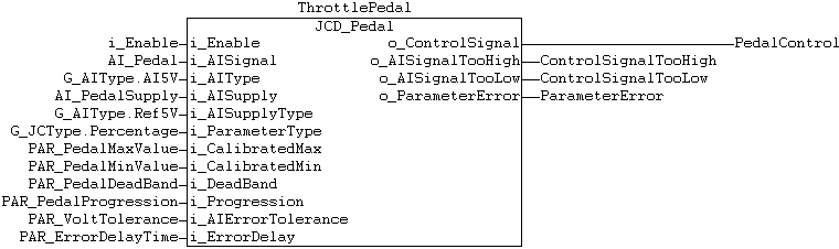
i_Enable |
BOOL |
FALSE/TRUE |
Enables controlling of o_ControlSignal
output |
i_AISignal |
UINT |
Hardware specific |
Analog input signal |
i_AIType |
BYTE |
0..G_ADScaleArrMax |
Analog input type and range |
i_AISupply |
UINT |
Hardware specific |
Pedal supply voltage measurement. |
i_AISupplyType |
BYTE |
0..G_ADScaleArrMax |
Pedal supply voltage type
and range. |
i_ParameterType |
BYTE |
G_JCType.Percentage, G_JCType.Voltage |
G_JCType.Voltage:
No voltage compensation, calibrated values are in volts.
G_JCType.Percentage:
Voltage compensation is in use. Calibrated values are percentage
of supply voltage. |
i_CalibratedMax |
UINT |
Hardware and calibration type
specific |
Maximum calibration value of joystick.
Value is given in voltage (1000 = 10,00V) or percentage (1000
= 100,0%), range depends on used hardware type. |
i_CalibratedMin |
UINT |
Hardware and calibration type
specific |
Minimum calibration value of joystick.
Value is given in voltage (1000 = 10,00V) or percentage (1000
= 100,0%), range depends on used hardware type. |
i_Deadband |
BYTE
|
0…100%
|
Dead band of pedal, value given
in percentage of max-min range. |
i_Progression |
SINT |
-100…100 |
Progression curve factor |
i_AIErrorTolerance |
INT |
-1,
0…250 or
-1,
0…500 depending on calibration type |
Defines
how many volts AI signal is allowed to be out of calibrated
range. Value is given in voltage (250 = 2,50V) or percentage
of supply voltage (500 = 50,0%), range depends on selected
value type. With value -1, diagnostics is not used. |
i_ErrorDelay |
UINT |
0…65535 ms |
The time that AI signal is allowed
to exceed tolerated range before error outputs are activated. |