This manual describes the full hardware version. Some of the features are optional and not implemented in all hardware versions.
|
This manual describes the full hardware version. Some of the features are optional and not implemented in all hardware versions. |
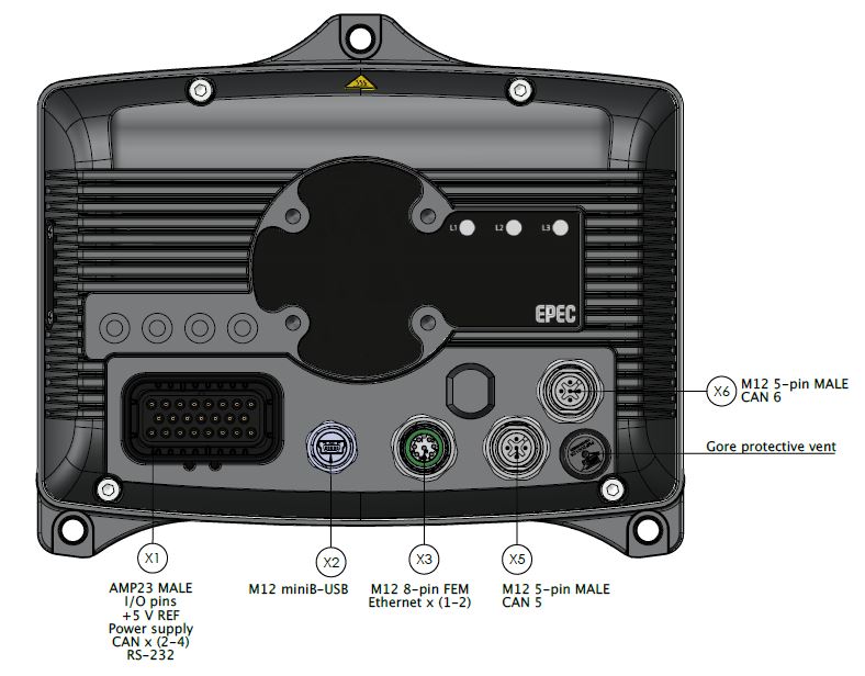
The connectors are placed in the unit according to the following figure:
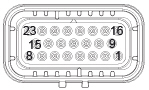
X1, AMP23 male connector (RS-232, CAN1, CAN2, CAN3, CAN4, DI, AI/DI, DO/DI, + 5V REF, power supply
Picture |
Pin |
Signal |
I/O Type |
|
1 |
CAN3_L |
|
2 |
CAN3_H |
|
|
3 |
RS-232_TXD |
|
|
4 |
RS-232_RXD |
|
|
5 |
CAN4_L |
|
|
6 |
CAN4_H |
|
|
7 |
CAN1_L |
|
|
8 |
CAN1_H |
|
|
9 |
DATA_GND |
|
|
10 |
DATA_GND |
|
|
11 |
DIGITAL_INPUT_1 |
||
12 |
DIGITAL_INPUT_2 |
||
13 |
CAN2_L |
|
|
14 |
CAN2_H |
|
|
15 |
CAN_SHIELD |
|
|
16 |
+5 V REF |
|
|
17 |
ANALOG_INPUT |
||
18 |
AI GND |
|
|
19 |
I/O_GND |
|
|
20 |
DIGITAL_OUTPUT_1 |
||
21 |
DIGITAL_OUTPUT_2 |
||
22 |
PWR_GND |
|
|
23 |
PWR_IN |
|
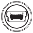
X2, mini-B-USB connector
Picture |
Pin |
Signal |
|
1 |
+5 V (max 500 mA) |
2 |
D- |
|
3 |
D+ |
|
4 |
ID |
|
5 |
GND |
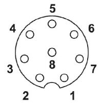
X3, M12 connector (8 pin FEM, ethernet)
Picture |
Pin |
Signal |
|
1 |
RD2+ |
2 |
TD2+ |
|
3 |
TD2- |
|
4 |
RD1- |
|
5 |
TD1+ |
|
6 |
RD1+ |
|
7 |
RD2- |
|
8 |
TD1- |
X5, M12 connector (5 pin MALE)
Picture |
Pin |
Signal |
|
1 |
CAN shield |
2 |
NC |
|
3 |
GND |
|
4 |
CAN5 H |
|
5 |
CAN5 L |
X6, M12 connector (5 pin MALE)
Picture |
Pin |
Signal |
|
1 |
CAN shield |
2 |
NC |
|
3 |
GND |
|
4 |
CAN6 H |
|
5 |
CAN6 L |