PWM/DO/CM_type086
Possible pin modes:
-
PWM mode with high side current measurement
-
DO mode
Select the mode using MultiTool Creator. MultiTool Creator generates the needed code using functions from SafeSSeriesIODriverExt library. For more information refer to Epec Programming and libraries Manual and MultiTool Creator Manual.
|
|
When using this type of pin, the power switch must be switched on as well. |
Output (PWM/DO)
-
This type of pin is a current sourcing output with a high side current measurement feature (the pin connects the load to a positive supply voltage through the shunt resistors).
-
These outputs have a switching element called a smart FET. It has integrated features to protect itself and also the external pin, wiring and actuator.
-
These outputs are capable of generating pulse width modulated (PWM) output signals.
-
When used as an output, the status feature indicates the output FET's state
|
|
The FET outputs are grouped into pairs:
The pairs are indicated with upper case characters in the pin table's Pair column in section I/O List |
|
|
It is recommended to use the function blocks in SafeSSeriesHardware library to protect and diagnose outputs when used as digital outputs. For more information, refer to Epec Programming and Libraries Manual. |
High side current measurement
-
The application can control the current with a current measurement feature
-
The firmware limits the maximum current to 3 A (when the current exceeds the value by more than the predefined time, the output is switched off)
Electrical characteristics
|
Symbol |
Parameter |
Conditions |
Min |
Max |
Units |
|
RShunt |
Shunt resistance |
|
typ. 15 |
mΩ |
|
|
Io-range |
Nominal Current Measuring Range |
|
0 |
3 |
A |
|
Iacc-zero |
Offset error |
Calculated 'worst case' |
+/-5,4 |
mA |
|
|
Iacc-prop |
Accuracy |
Calculated 'worst case' |
+/-2 |
% (FS) |
|
|
Io |
Nominal Output Current |
Output On |
0 |
2,5 |
A |
|
Io-lim |
Internal current limitation |
Output On (Note 6) |
|
3 |
A |
|
Ileak
|
Leakage Current |
|
|
40 |
µA |
|
fPWM |
PWM Frequency |
In current control mode (Note 1) |
10 |
400 |
Hz |
|
In PWM mode (Note 1) |
10 |
2500 |
Hz |
||
|
DutyPWM |
PWM |
(Note 2, 8) |
0 to 100 |
% |
|
|
ResPWM |
PWM Resolution |
(Note 3) |
0,1 |
% |
|
|
Digital status |
|||||
|
RI |
Resistance |
Output Off |
typ. 8 |
kΩ |
|
|
VH |
Digital status |
Output Off |
3,57 |
|
V |
|
VL |
Digital status |
Output Off |
|
1,42 |
V |
|
CO |
Output pin capacitance |
|
typ. 1 |
nF |
|
Note 1: Frequency of a (PWM) Pulse Width Modulation is = 1 / Period
Note 2: The duty cycle is defined as the percentage of digital ‘high’ to digital ‘low’ signals present during a PWM period.
Note 3: The PWM resolution is defined as the maximum number of pulses that you can pack into a PWM period.
Note 4: tC denotes software cycle time.
Note 5: The maximum output current depends on the load, PWM frequency and temperature.
Note 6: Firmware protects the internal shunt resistor in case of overcurrent. Firmware overcurrent protection reacts typically within 10-20ms in case the current exceeds 3A. This over current limit cannot be adjusted by software and is meant only for protection of the hardware. It is possible to set the lower limiting value for overcurrent protection in the application by using current feedback and ready library POUs.
Note 7: When both outputs in the pair are used, the maximum continuous current for the pair is 4 A.
Note 8: When the frequency increases, the actual duty cycle may be bigger than the value that has been set due to inherent delays of the hardware.
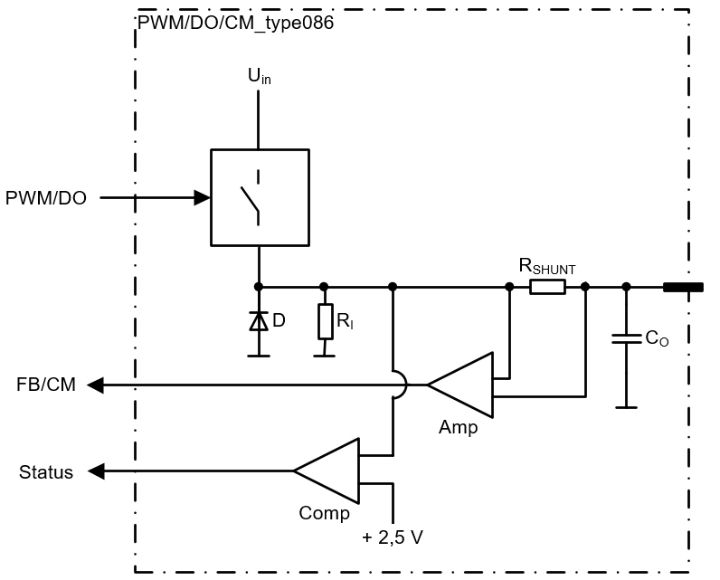
Functional block diagram