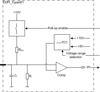
This type of pin is a ground referenced input (DI) including a pulse counting (PI) feature.
Pulse inputs can be used as a 1 or 2 channel pulse counter and they have a reset possibility. Possible software channels and pairs are listed in section SW channels for Pulse Inputs.
The configurable features are controlled by two control signals:
pull-up enable selection
input voltage range selection
When the pull-up to internal +10V is enabled, it controls two input pins as one. The pairs are indicated with lower case characters in the pin table's Group column in section Pinout Map.
The input voltage range selection controls two input pins as one. This local signal defines threshold voltage levels for both inputs. This feature provides more flexibility to sensor connections. The pairs are indicated with lower case characters in the pin table's Group column in section Pinout Map.
Electrical characteristics
|
Symbol |
Parameter |
Conditions |
Min |
Max |
Units |
|
RI |
Input Resistance |
Referenced to GND (Note 1) |
typ. 12,4 |
kΩ |
|
|
RPU |
Pull-up Resistance |
Referenced to +10V |
typ. 2,2 |
kΩ |
|
|
VLevel |
Output voltage |
Unconnected pin, +10V_PU enabled (Note 2) |
typ. 8,3 |
V |
|
|
VIH |
Input High Voltage level |
+10V range (Note 3) |
7,0 |
50 |
V |
|
VIL |
Input Low Voltage level |
+10V range |
0,0 |
5,0 |
V |
|
VIH |
Input High Voltage level |
+5V range (Note 3) |
3,9 |
50 |
V |
|
VIL |
Input Low Voltage level |
+5V range |
0,0 |
2,8 |
V |
|
VI-max |
Max Input voltage |
(Note 6) |
-5 |
60 |
V |
|
fI |
Input Frequency |
tC = 4 ms (Note 4, 5, 8, 9) |
|
250 |
Hz |
|
Input Frequency |
(Note 7, 10) |
5 |
20000 |
Hz |
|
|
tI |
Input Pulse Width (pulse counting) |
(Note 7) |
0,025 |
250 |
ms |
|
CI |
Input pin capacitance |
|
typ. 1 |
nF |
|
Note 1: A pull-up resistor is not selected.
Note 2: When pull-up resistor is selected.
Note 3: Exceeding the max values might cause damage to input.
Note 4: These parameters depend on software cycle time.
Note 5: Applies to inputs used as normal digital input. Violating this rating may lead to application program not noticing all input state transitions.
Note 6: Overload conditions.
Note 7: Violating this rating may lead to system not recognizing all input state transitions.
Note 8: Pulse width must be greater that the software cycle time. For example with 50/50 pulse ratio, the pulse frequency is 1 / (2*pulse width)
Note 9: tC denotes software cycle time.
Note10: Max value can be reached by 2-98% pulse ration.
|
|
Refer to section Connection Examples to see examples of how to connect external actuators or sensors when using this type of pin. |