|
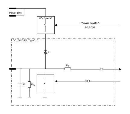
When using this type of pin, the related power switch must be switched on as well. See related power switches in section I/O List table's column named Group. Before the supply voltage can be connected to an output pin, the related power switch must be on. If the related power switch is off, the pin's input state is 1 (TRUE).
|
This type of pin is a current sinking output
In other words, this type of output connects the loads to the ground (GND) and simultaneously the state of the output can be monitored with an input.
|
It is recommended to use the function blocks in DigitalOutputDiagnostics library to protect and diagnose outputs when used as digital outputs. For more information, refer to Epec Programming and Libraries Manual. |
This type of pin can also be used as an input
In this case, the output functionality of the pin must be kept in the off state.
It must be taken care in system design that the output unintentionally switching to on state causes no harm to the system.
Electrical characteristics
Symbol |
Parameter |
Conditions |
Min |
Max |
Units |
RON |
On-resistance |
Output On |
|
250 |
mΩ |
II |
Nominal Input Current |
Output On, VDCLOAD < max VI-range |
0 |
3 |
A |
Digital status input |
|||||
RI |
Input Resistance |
Output Off |
typ. 12,4 |
kΩ |
|
VIH |
Digital status input |
Output Off (Note 2) |
3,2 |
|
V |
VIL |
Digital status input |
Output Off |
|
1,4 |
V |
VI-range |
Input voltage range |
(Note 2) |
-0,5 |
Uin + 0,2V |
V |
tI-status |
Time Constant of Status Low Pass Filter |
Output Off |
typ. 1,55 |
ms |
|
CI |
Input Capacitance |
|
typ. 1 |
nF |
Note 1: Parameter is defined by resistive load.
Note 2: Exceeding the max value might cause damage to input.
|
Refer to section Connection Examples to see examples of how to connect external actuators or sensors when using this type of pin. |