![]()
Supported features are product specific depending on the used libraries. In CODESYS 3.5, device description defines the used library.
Configurations for SAE J1939 communication protocol are done in CAN and J1939 tabs.
NMEA 2000NMEA 2000 messages are defined in NMEA 2000 tab.
NMEA 2000 is communication protocol for marine industry. It is based on SAE J1939 protocol, but it defines own messages. It contains also own transfer method “NMEA 2000 fast packet” for multi-frame parameter groups. The fast packet transfer is implemented in Epec J1939 library.
MultiTool Creator’s offers possibility to configure NMEA 2000 rx and tx PGNs for Epec control units.
This topic describes
the needed actions to configure a device to receive and transmit J1939 or NMEA 2000 messages
J1939 general settings are defined in CAN tab's J1939 subtab. Currently it contains only one setting.
|
|
Supported features are product specific depending on the used libraries. In CODESYS 3.5, device description defines the used library. |
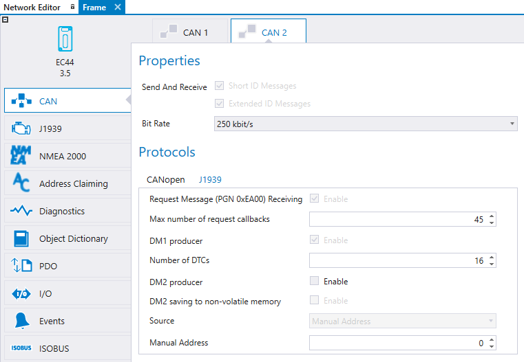
First select the CAN channel from the tabs and then select J1939 subtab.
|
Property |
Description |
|
Request Message (PGN 0xEA00) Receiving |
Enable J1939 Request Message receiving. Should be enabled if some other device uses Request PGN message to request specific PGN transmission from this unit. Note! Selection is enabled automatically if Address Claiming is defined to use. |
|
Max number of request callbacks |
The maximum number of request callbacks that are allowed |
|
DM1 producer |
Enables DM1 producer (currently active) |
|
Number of DTCs |
The maximum number of simultaneousely active Diagnostic Trouble Codes. |
|
DM2 producer |
Enables DM2 producer (history) |
|
DM2 saving to non volatile memory |
Enables saving DM2 to non volatile memory |
|
Source |
Source address to use for the DM producer |
|
Manual Address |
If Source is sent to manual address, this field defines the address. |
1. Add a J1939/NMEA 2000 device. To add the J1939/NMEA 2000 device, select ![]() icon on the Network Editor.
icon on the Network Editor.

2. Selecting the created J1939/NMEA 2000 device opens J1939 Device Properties on the left. Give a descriptive name and J1939/NMEA 2000 address for the device.
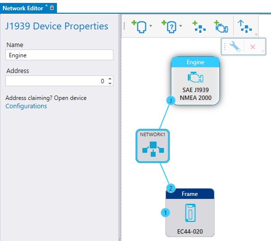
If the J1939 device uses Address Claiming protocol double click the J1939 device to open the configuration window. Note that the configuration window is available only if J1939/NMEA 2000 device is connected to a network which contains at least one programmable unit with Address Claiming procol support.
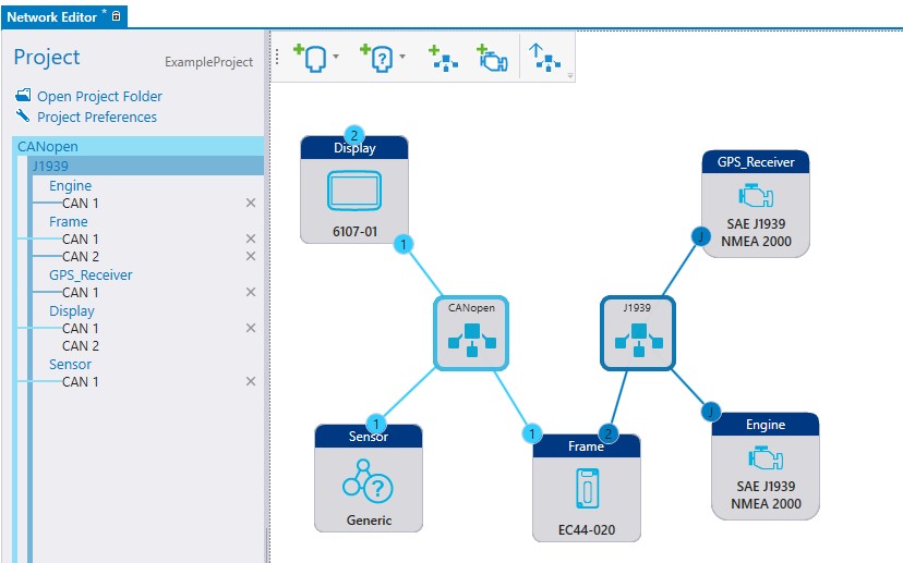
3. Add the J1939/NMEA 2000 device into network if not already added.
4. Configure the CAN bus
Since the J1939 protocol uses extended identifiers (29 bit) in messages, make sure that the device has CAN > Send and Receive > Extended ID Messages property selected for the CAN channel.
CODESYS 3.5 programmable devices always receive both Short and Extended ID messages.
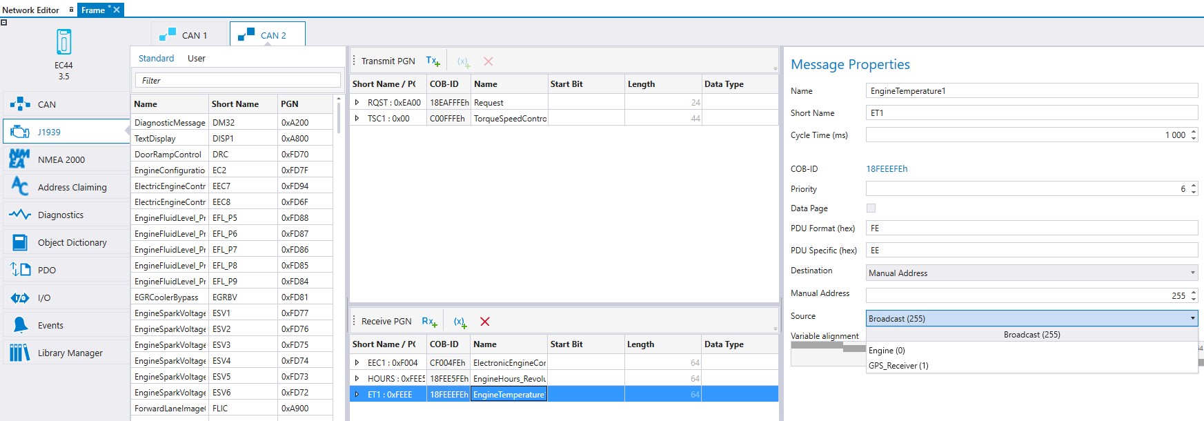
5. After the CAN configuration, J1939 PGN messages can be configured to be transmitted or received on the J1939 tab. To add a receive PGN,
Select the J1939 tab and the correct CAN channel
The PGN messages are listed on the left. Select the PGN message from the Standard list (in this example ET1). User list contains the user specific list, directory paths for the list is defined in Settings.
Drag and drop the selected PGN message to the Receive PGN table, see the following picture
![]()
Select a PGN from the Receive PGN table and make the configurations to the J1939 Message Properties on the right side. To receive a message (in this example ET1) from the Engine device, define Engine to be the Source on the J1939 Message Properties.
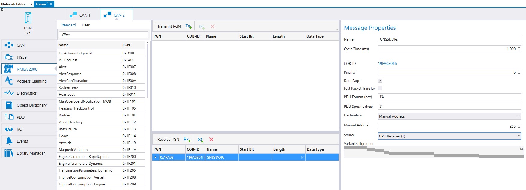
6. NMEA 2000 PGN messages can be configured to be transmitted or received on the NMEA 2000 tab.
Select the NMEA 2000 tab and the correct CAN channel
The PGN messages can be selected same way than in J1939 tab. Select the PGN message from the list and drag and drop the selected PGN message to the Receive PGN or to the Transmit PGN table.
User list contains the user specified list, directory paths for the list is defined in Settings. Both J1939 and NMEA 2000 have own user PGN sets.
To create user PGN sets:
Select messages from Transmit PGN or Receive PGN table (press CTRL to select multiple messages)
Right-click and select Add to PGN Set.

Select a set or give a name for a new set and click OK
For a new PGN Set: MultiTool Creator creates a new PGN file to the default directory given in Settings.
For existing PGN Set: The messages are added to the end of the set.
The xml file for a PGN set can also be created manually.
It is possible drag-and-drop complete PGN sets from User list to Transmit PGN or Receive PGN table
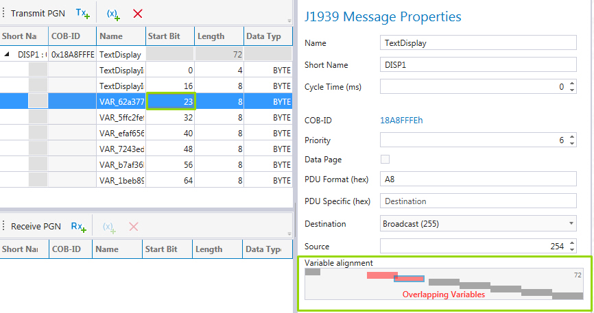
The J1939 Message Properties are described in the following table:
|
J1939 Message Property |
Description |
|
Name |
Full name of the PGN.
|
|
Short Name |
Short name of the PGN to be used as an identifier in the PGN list. The short name has to be unique.
|
|
Cycle Time (ms) |
Cycle time can be selected from range 0-65535 ms. Cycle Time 0 ms means that the message is not automatically sent. When configuring - a transmit PGN, the cycle time defines the time that must elapse between two consecutive messages. - a receive PGN, the cycle time defines the monitoring interval for the messages by multiplying the given cycle time by three. For example if the given cycle time is 100 ms, the device waits for 300 ms before giving a time out flag.
|
|
COB-ID |
Shows the whole message ID that contains the given Priority, Data Page, PDU Format, PDU Specific/Destination address.
|
|
Priority (hex) |
Select a priority for the message. Number 0 is the highest priority and 7 the lowest.
|
|
Data Page |
This doubles the number of possible parameter groups that can be represented by the identifier.
|
|
PDU Format |
The PDU Format (PDUF) defines whether the message is transmitted with a destination address or if the message is always transmitted as a broadcast message. The interpretation of the PDU Specific (PDUS) field depends on the PDU Format value. If the PDUF value is
|
|
PDU Specific |
The interpretation of the PDU Specific (PDUS) field depends on the PDU Format (PDUF) value. If the PDUF value is
|
|
Destination |
Select the destination of the message from the Destination drop-down list. In case of a
|
|
Source |
Select the source of the message from the Source drop-down list. In case of a
|
|
Manual Address |
In case of a
|
|
Generate SPNs to fill 8 bytes |
If selected, dummy variables are created to make the PGN 8 bytes long. |
|
Set unused bits to 1 |
If selected, all bits of the dummy variables are set to 1. |
|
Variable Alignment |
Variable Alignment diagram indicates if some of the variables are overlapping each other. Adjust the Start Bit or Length if needed to prevent overlapping.
|
|
NMEA 2000 Message Property |
Description |
|
Name |
Full name of the PGN.
|
|
Cycle Time (ms) |
Cycle time can be selected from range 0-65535 ms. Cycle Time 0 ms means that the message is not automatically sent. When configuring - a transmit PGN, the cycle time defines the time that must elapse between two consecutive messages. - a receive PGN, the cycle time defines the monitoring interval for the messages by multiplying the given cycle time by three. For example if the given cycle time is 100 ms, the device waits for 300 ms before giving a time out flag.
|
|
COB-ID |
Shows the whole message ID that contains the given Priority, Data Page, PDU Format, PDU Specific/Destination address.
|
|
Priority (hex) |
Select a priority for the message. Number 0 is the highest priority and 7 the lowest.
|
|
Data Page |
This doubles the number of possible parameter groups that can be represented by the identifier. |
|
Fast Packet Transfer |
NMEA 2000 fast transfer protocol selection. |
|
PDU Format |
The PDU Format (PDUF) defines whether the message is transmitted with a destination address or if the message is always transmitted as a broadcast message. The interpretation of the PDU Specific (PDUS) field depends on the PDU Format value. If the PDUF value is
|
|
PDU Specific |
The interpretation of the PDU Specific (PDUS) field depends on the PDU Format (PDUF) value. If the PDUF value is
|
|
Destination |
Select the destination of the message from the Destination drop-down list. In case of a
|
|
Source |
Select the source of the message from the Source drop-down list. In case of a
|
|
Manual Address |
In case of a
|
|
Variable Alignment |
Variable Alignment diagram indicates if some of the variables are overlapping each other. Adjust the Start Bit or Length if needed to prevent overlapping.
|
Transmit and Receive PGNs can also be added manually:
Select![]() icon from Transmit PGN section or
icon from Transmit PGN section or ![]() icon from Receive PGN section
icon from Receive PGN section
Select the added PGN and define the Message Properties
Add PGN variables by selecting ![]() icon.
icon.
To add a new variable into a PGN, select the message and select ![]() icon. The configurable properties for PGN variables are described in the following table:
icon. The configurable properties for PGN variables are described in the following table:
|
PGN variable properties |
Description |
|
Name |
Variable name used in CODESYS with the prefix J1939_ |
|
Start Bit |
The variable's defined start bit. |
|
Length (bits) |
Variable's length in bits. |
|
Data Type |
Variable type. The variable type selection depends on the given bit length. |
To remove a PGN message, select the PGN and press ![]() icon or click DELETE.
icon or click DELETE.
Epec Oy reserves all rights for improvements without prior notice.
Source file topic200010.htm
Last updated 3-Sep-2025