Supported platforms: CODESYS 3.5, CODESYS 3.5 SAFETY, CODESYS 3.5 SP19 SAFETY
S_Joystick (FB)
Description
This function block scales joystick voltage to control the value between -10000 – (+)10000. The function block also contains the functionality for output signal progression, joystick dead band, input voltage range diagnostics, calibration mode and prevention of unexpected movement after startup.
Initialization
Init method is used to initialize the necessary static calculation parameters for the function block instance.
The method shall be called at least once before the actual function block can be called, i.e. at the application initialization phase.
The method checks the validity of input parameters. However, none of the function block outputs are affected by the initialization.
|

|
A parameter error is diagnosed if:
-
Init method is not called before the main FB call OR
-
i_pEventCode = 0 OR
-
S_i_pCalibratedMinPosition = 0 OR
-
S_i_pCalibratedMidPosition = 0 OR
-
S_i_pCalibratedMaxPosition = 0 OR
-
S_i_DeadBand out of range OR
-
S_i_ProgressionPosDir out of range OR
-
S_i_ProgressionNegDir out of range OR
-
S_i_SignalErrorTolerance out of range OR
-
CalibratedMinPosition out of range (allowed range 0-500‰) OR
-
CalibratedMidPosition out of range (allowed range 250-750‰) OR
-
CalibratedMaxPosition out of range (allowed range 500-1000‰) OR
-
CalibratedMinPosition > CalibratedMidPosition OR
-
CalibratedMidPosition > CalibratedMaxPosition
|
Initialization parameters
|
Parameter
|
Type
|
Unit
|
Range
|
Description
|
|
S_i_Deadband
|
SAFEDINT
|
‰
|
0 - 500
|
Joystick dead band in middle position. Value given in per mil of maximum - middle or middle - minimum range.
|
|
S_i_ProgressionPosDir
|
SAFEDINT
|
-
|
-100 - (+)100
|
Positive direction’s progression curve factor
|
|
S_i_ProgressionNegDir
|
SAFEDINT
|
-
|
-100 - (+)100
|
Negative direction’s progression curve factor
|
|
S_i_SignalErrorTolerance
|
SAFEDINT
|
‰
|
0-1000
|
Defines how much signal voltage can be exceed the calibrated range before it is interpreted as error situation.
|
|
S_i_pCalibratedMinPosition
|
Pointer to SAFEDINT
|
-
|
≠ 0
|
Pointer to minimum calibration value of joystick. Value given as per mil from reference voltage, with range 0-500‰.
|
|
S_i_pCalibratedMidPosition
|
Pointer to SAFEDINT
|
-
|
≠ 0
|
Pointer to middle calibration value of joystick. Value given as per mil from reference voltage, with range 250-750‰.
|
|
S_i_pCalibratedMaxPosition
|
Pointer to SAFEDINT
|
-
|
≠ 0
|
Pointer to maximum calibration value of joystick. Value given as per mil from reference voltage, with range 500-1000‰.
|
|
i_pEventCode
|
POINTER TO EventCode
|
-
|
≠ 0
|
Pointer to application variable which is type EventCode.
|
Initialization method return value
|
TRUE: All initialization parameters ok.
|
|
FALSE: Error in initialization parameter(s).
|
Calibration
When i_Enable is TRUE, and the parameter error is not active, the joystick calibration is started at the rising edge of i_CalibrationMode.
At the beginning of calibration, the calibration flags and values are reset.
During calibration, the joystick signal minimum and maximum values are measured and stored into internal variables. The released (i.e. center) position value is measured and stored into an internal variable when the calibration ends. The calibration ends at the falling edge of i_CalibrationMode.
The minimum, maximum and released position values are checked for consistency.
If the values are ok,
-
they are copied to application variables pointed by S_i_pCalibratedMinPosition, S_i_pCalibratedMidPosition and S_i_pCalibratedMaxPosition
-
CalibrationDone status is set
If the values are not ok,
The calibration can be cancelled by setting the input i_Enable to FALSE on the same program cycle or earlier than the input i_CalibrationMode is set to FALSE. In this case, the calibration values are not changed.
Operation
When i_Enable is TRUE, parameter error is not active, and calibration values are ok, the function block calculates the control value from the signal voltage.
Scaling
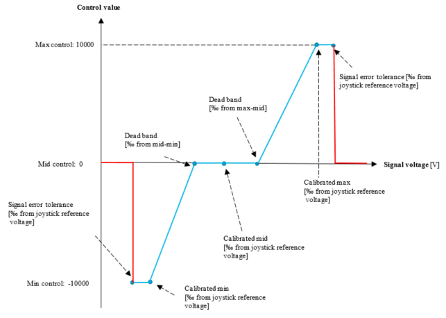
The function block scales input voltage i_Voltage linearly to control value 0-10000 by using inputs i_VoltageForMaxControl, i_VoltageForMinControl and i_Deadband. Equation 1 is used to calculate the control value in case of a positive slope and when the voltage is over the dead band limit.

, where ControlMax = 10000,

, and

Equation 2 is used to calculate the control value in case of negative slope and when the input voltage is lower than the dead band voltage limit.

, where ControlMax = 10000,

, and

Progression
The function block adjusts S_o_Control value according to the progression factor.
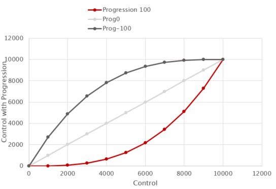
Equation 3 is used for positive progression.
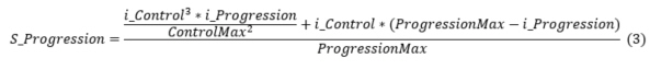
Equation 4 is used for negative progression.

Inputs
|
Input variable name
|
Data type
|
Unit
|
Range
|
Description
|
|
i_Enable
|
BOOL
|
-
|
-
|
Enables control output.
|
|
S_i_SignalVoltage
|
SAFEDINT
|
mV
|
>= 0
|
Voltage measured from joystick output pin.
|
|
S_i_ReferenceVoltage
|
SAFEDINT
|
mV
|
> 0
|
Voltage measured from joystick supply pin.
|
|
i_CalibrationMode
|
BOOL
|
-
|
-
|
Enables calibration of output signal.
|
Outputs
|
Output variable name
|
Data type
|
Unit
|
Range
|
Description
|
|
S_o_Control
|
SAFEINT
|
-
|
-10000 - (+)10000
|
Calculated control value
|
|
o_Status
|
Status
|
-
|
-
|
Status of output value. See Status structure.
|
Error diagnostic
See Diagnostic Interface library description of error status and event code functionality.
|
Conditions
|
S_o_
Control
|
o_Status. OutputValid
|
o_Status error status
|
Event code FunctionID
|
Event code EventID
|
|
i_Enable TRUE
AND
init parameter error AND
i_pEventCode valid
|
0
|
FALSE
|
ParameterError
|
JOYSTICK
|
PARAMETER_ERROR
|
|
i_Enable TRUE
AND
init parameter error AND
i_pEventCode NULL
|
0
|
FALSE
|
ParameterError
|
-
|
-
|
|
i_Enable rises AND
init parameters ok AND
signal voltage outside dead band
|
0
|
FALSE
|
StartupError
|
JOYSTICK
|
STARTUP_ERROR
|
|
i_Enable rises AND
init parameters ok AND
signal voltage within dead band
|
Scaled control value
|
TRUE
|
-
|
NO_FUNC
|
NO_ERROR
|
|
i_Enable TRUE AND
init parameters ok AND
no startup error AND
signal > calibrated maximum value + error tolerance
|
0
|
FALSE
|
SignalTooHigh
|
JOYSTICK
|
INPUT_TOO_HIGH
|
|
i_Enable TRUE AND
init parameters ok AND
no startup error AND
signal < calibrated minimum value - error tolerance
|
0
|
FALSE
|
SignalTooLow
|
JOYSTICK
|
INPUT_TOO_LOW
|
Example code
|
Safe definitions:
|
|
VAR_INPUT
i_Enable: BOOL; (* Enable signal from S_ValidateAI o_Status output *)
i_SignalVolt: SAFEDINT; (* Voltage signal from S_ValidateAI S_o_Output *)
i_RefVolt: SAFEDINT; (* Reference voltage 5V*)
i_CalibMode: BOOL; (* Activate calibration mode *)
END_VAR
VAR_OUTPUT
o_Steering: SAFEINT; (* Steering value -10000..10000 *)
END_VAR
VAR
steeringJoystick: EPEC_SJCD.S_Joystick;
(*NOTE! Calibration points, deadband, progression and error tolerance are usually machine parameters, not POU internal variables*)
deadBand: SAFEDINT:=50;
progression: SAFEDINT:=0;
signalErrorTolerance: SAFEDINT:=20;
calibMinPosition: SAFEDINT:=100; (* Calibration min value *)
calibMinPosition: SAFEDINT:=500; (* Calibration mid value *)
calibMaxPosition: SAFEDINT:=900; (* Calibration max value *)
ec_Joystick: EPEC_DITF.EventCode;
initRetVal: BOOL; (* return value of init method *)
END_VAR
|
|
Init at safe PRG:
|
|
initRetVal:=steeringJoystick.Init(
S_i_Deadband:=deadBand ,
S_i_Progression:=progression ,
S_i_SignalErrorTolerance:=signalErrorTolerance ,
S_i_pCalibratedMinPosition:=ADR(calibMinPosition) ,
S_i_pCalibratedMidPosition:=ADR(calibMidPosition) ,
S_i_pCalibratedMaxPosition:=ADR(calibMaxPosition) ,
i_pEventCode:=ADR(ec_Joystick) );
|
|
|
|
Code at safe PRG:
|
|
steeringJoystick(
i_Enable:=i_Enable ,
S_i_SignalVoltage:=i_SignalVolt ,
S_i_ReferenceVoltage:= i_RefVolt,
i_CalibrationMode:= i_CalibMode,
S_o_Control=> o_Steering,
o_Status=> );
|
See also
Source file topic100401.htm
Last updated 4-Sep-2025