Supported platforms: CODESYS 3.5, CODESYS 3.5 SAFETY, CODESYS 3.5 SP19 SAFETY
S_VoltageToResistance (FB)
Description
This function block is used to calculate the resistance of sensor which is connected to control unit AI pin.
Sensor resistance is calculated from measured pin voltage.
Typical use of the function block is to calculate the resistance of different temperature sensors:
- PT temperature sensors: PT500, PT1000 and PT2000
- KTY sensors: KTY1000 and KTY2000
Initialization
Init method is used to initialize the necessary static calculation parameters for the function block instance.
The method shall be called at least once before the actual function block can be called, i.e. at the application initialization phase.
The method checks the validity of input parameters. However, none of the function block outputs are affected by the initialization.
|

|
A parameter error is diagnosed if:
-
Init method is not called before the main FB call OR
-
i_pEventCode = 0 OR
-
S_i_OutputResistanceLow >= S_i_OutputResistanceHigh OR
-
S_i_OutputResistanceLow < 0 OR
-
S_i_OutputResistanceHigh <= 0
|
Initialization parameters
|
Parameter
|
Type
|
Unit
|
Range
|
Description
|
|
S_i_InternalPullUpResistance
|
ENUM
|
Ω
|
EPEC_HW.
PULL_UP_
RESISTANCE
|
Internal pull-up resistance value of the input pin
|
|
S_i_InternalPullDownResistance
|
ENUM
|
Ω
|
EPEC_HW.
PULL_UP_
RESISTANCE
|
Internal pull-down resistance value of the input pin
|
|
S_i_OutputResistanceHigh
|
SAFEDINT
|
Ω
|
>0
|
Limit value for status o_Status.OutputTooHigh
|
|
S_i_OutputResistanceLow
|
SAFEDINT
|
Ω
|
>=0
|
Limit value for status o_Status.OutputTooLow
|
|
S_i_DiagnosticDelay
|
SAFEUINT
|
ms
|
-
|
Delay time for output high/low diagnostics
|
|
i_pEventCode
|
POINTER TO EventCode
|
-
|
≠0
|
Pointer to application variable which is type EventCode.
|
Initialization method return value
|
TRUE: All initialization parameters ok.
|
|
FALSE: Error in initialization parameter(s).
|
Operation
When i_Enable is TRUE, the function block calculates the resistance (Ohm) value from voltage values of sensor and reference pins.
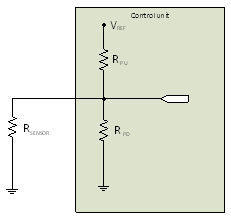
Figure 1. Voltage input with internal pull-up and pull-down resistances.
The sensor resistance can be calculated from equation 1
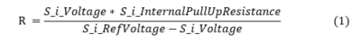
, where R is total resistance of RSENSOR (and parallel RPULLDOWN, if exists).
If a pull-down resistor exists, the sensor resistance can be calculated from equation 2
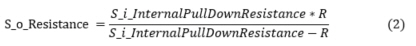
, where R is the result of the equation 1. Parameter error is activated if pull-down resistor exists, but its value S_i_InternalPullDownResistance ≤ R.
If the calculated resistance is lower than S_i_OutputResistanceLow or higher than S_i_OutputResistanceHigh for longer (≥) than given diagnostic delay time, the corresponding error output is set.
The output S_o_Resistance is set to safe value (0) if any error occurs, also o_Status.OutputValid is set false and the corresponding event ID is set to EventCode.
Limitations
|

|
The used AI pin must be configured to voltage mode.
|
Inputs
|
Input variable name
|
Data type
|
Unit
|
Range
|
Description
|
|
i_Enable
|
BOOL
|
-
|
TRUE / FALSE
|
Enable calculation
|
|
S_i_Voltage
|
SAFEDINT
|
mV
|
>=0
|
Sensor voltage value
|
|
S_i_RefVoltage
|
SAFEDINT
|
mV
|
>0
|
Reference pin voltage value (=supply of the sensor)
|
Outputs
|
Output variable name
|
Data type
|
Unit
|
Range
|
Description
|
|
S_o_Resistance
|
SAFEDINT
|
mΩ
|
>=0
|
Calculated resistance value
|
|
o_Status
|
Status
|
-
|
-
|
Status of output value. See Status structure.
|
Error diagnostic
See Diagnostic Interface library description of error status and event code functionality.
|
Conditions
|
S_o_
Resistance
|
o_Status. OutputValid
|
o_Status error status
|
Event code FunctionID
|
Event code EventID
|
|
i_Enable TRUE
AND
init parameter error AND
i_pEventCode valid
|
0
|
FALSE
|
ParameterError
|
VOLTAGE_TO_ RESISTANCE
|
PARAMETER_ERROR
|
|
i_Enable TRUE
AND
init parameter error AND
i_pEventCode NULL
|
0
|
FALSE
|
ParameterError
|
-
|
-
|
|
i_Enable rises
AND
init parameters ok AND
S_i_OutputResistanceLow <= S_o_Resistance <= S_i_OutputResistanceHigh
|
calculated value
|
TRUE
|
-
|
NO_FUNC
|
NO_ERROR
|
|
S_i_Voltage >= S_i_RefVoltage OR
S_i_InternalPullDownResistance <= R (see equation 2)
|
0
|
FALSE
|
ParameterError
|
VOLTAGE_TO_ RESISTANCE
|
PARAMETER_ERROR
|
|
i_Enable TRUE
AND
parameters ok
AND
S_o_Resistance > S_i_OutputResistanceHigh
|
0
|
FALSE
|
OutputHigh
|
VOLTAGE_TO_ RESISTANCE
|
OUTPUT_TOO_HIGH
|
|
i_Enable TRUE
AND
parameters ok
AND
S_o_Resistance < S_i_OutputResistanceLow
|
0
|
FALSE
|
OutputLow
|
VOLTAGE_TO_ RESISTANCE
|
OUTPUT_TOO_LOW
|
Example code
|
|
MultiTool Creator code template includes resistance conversion for products which support TI mode. In products without TI mode support the resistance conversion is handled by application. For more information see How to validate temperature sensors.
|
|
|
This FB's input data is voltage. The voltage value needs to be converted from AD value with S_ADCToVoltageOrCurrent (FB).
|
|
|
Location of the POU instance depends on the application: Non-safe inputs are handled in non-safe context, safe inputs are handled in safe context. The example code applies to both.
|
|
Definitions:
|
|
|
VAR_INPUT
S_i_XM1_3_Voltage: SAFEDINT; // Input voltage
S_i_RefVoltage: SAFEDINT; // Sensor supply voltage (not 5V ref..)
END_VAR
VAR_OUTPUT
S_o_XM1_3_Resistance: SAFEDINT; // Measured resistance
o_XM1_3_Status_ToResistance: EPEC_SC.Status; // Conversion status
o_EC_XM1_3: EPEC_DITF.EventCode; // Event code of the input
END_VAR
VAR
init_ok: BOOL := FALSE;
S_1_3_ToResistance: EPEC_SC.S_VoltageToResistance;
END_VAR
VAR CONSTANT
SENSOR_RESISTANCE_HIGH: SAFEDINT := DINT#3000; // Resistance high error limit (Ohm)
SENSOR_RESISTANCE_LOW: SAFEDINT := DINT#500; // Resistance low error limit (Ohm)
END_VAR
|
|
|
|
Init:
|
|
|
o_EC_XM1_3.DeviceID := BYTE#3;
o_EC_XM1_3.ChannelID := BYTE#0;
o_EC_XM1_3.FunctionID := EPEC_DITF.FunctionIDs.NO_FUNC;
o_EC_XM1_3.EventID := EPEC_DITF.ErrorIDs.NO_ERROR;
init_ok := S_1_3_VoltageToResistance.Init(
S_i_InternalPullUpResistance := EPED_HW.PULL_UP_RESISTANCE.R_2K2,
S_i_InternalPullDownResistance := EPED_HW.PULL_DOWN_RESISTANCE.R_82K,
S_i_OutputResistanceHigh := SENSOR_RESISTANCE_HIGH,
S_i_OutputResistanceLow := SENSOR_RESISTANCE_LOW,
S_i_DiagnosticDelay := EPEC_HW.Constants.G_VOLTAGE_INPUT_DIAGNOSTIC_DELAY,
i_pEventCode := ADR(o_EC_XM1_3)
);
|
|
Code:
|
|
|
S_1_3_VoltageToResistance(
i_Enable := init_ok,
S_i_Voltage := i_XM1_3_Voltage,
S_i_RefVoltage := S_i_RefVoltage,
o_Status => o_XM1_3_Status_ToResistance,
S_o_Resistance => S_o_XM1_3_Resistance
);
|
See also