This chapter describes the needed installations and steps to create a small program to an Epec unit with MultiTool Creator and CODESYS.
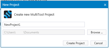
1. Open MultiTool Creator and create a New Project from the Start Page or using the File menu

MultiTool Creator automatically creates a project folder with the project name.
The project folder will be created into the default path. The project path can be changed by selecting Browse...
To change the suggested default project path, open MultiTool Settings File > Settings > Environment > Default Project Path
2. To add the device(s), click Add Device 
At this point, the device type, functional version and used CODESYS version should be known. MultiTool Creator adds a device template that is ready to be configured.
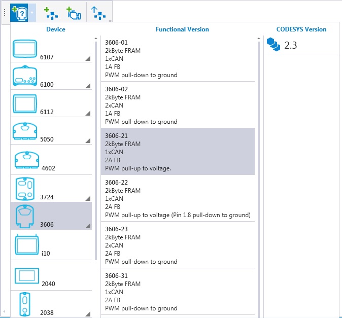
MultiTool Creator automatically creates names for the devices, but they can also be renamed. It is always recommended to rename the devices to describe their functionality in the system. To rename the device, select the device and change the name in Device Properties > Device Name.
3. Save the project from the File menu or with CTRL+S.
4. Define a network
The network definition is needed if the system includes several devices. To add a new network, click Add Network  .
.
Connect the device to the network by dragging a CAN channel from the device and drag the cursor on a network. The connection is added.
5. Double-click the device to configure it. The Device Configuration opens as a new tab next to the Network Editor.
-
Select the used Application Node-ID on the CAN tab
-
Select the device to be an NMT master or slave in the network on the CAN tab
-
Select monitored nodes on the CAN tab
-
Add variables and parameters to index(es) and subindex(es) on the Object Dictionary tab
-
Define the variables to be transmitted in PDOs for other devices on the PDO tab
6. To create the CODESYS project directly from MultiTool Creator, select the device and then  icon from the hover menu.
Create CODESYS Project launches CODESYS, creates a project template and imports all MultiTool Creator configurations to the code template.
1. Create CODESYS Project launches CODESYS, creates a project template and imports all MultiTool Creator configurations to the code template.
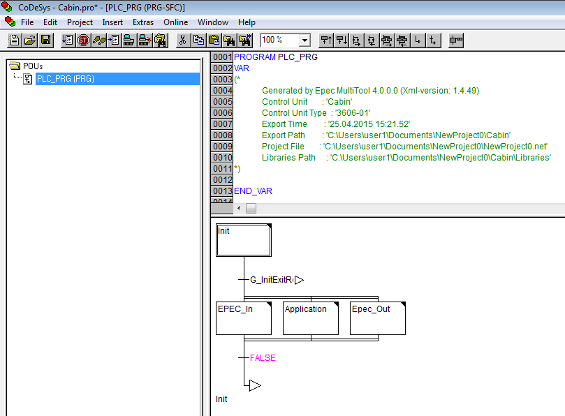
2. PLC_PRG's action called Application automatically calls a program called Main that the user needs to create first.
To add Main program, right-click POUs section and select Add Object…
Name the POU as Main and define the programming language to FBD (Function Block Diagram).

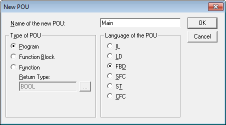
3. Double-click Main program to open it and add a box right-clicking the first network.
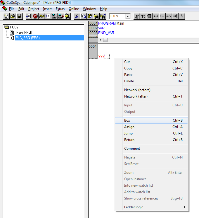
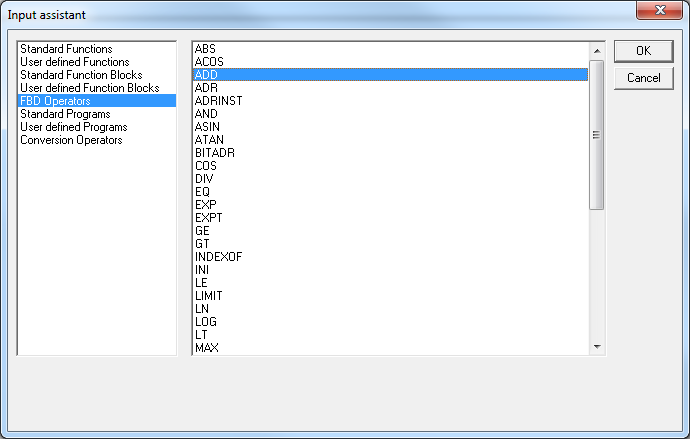
4. CODESYS automatically suggests an operator AND. To change it, select AND text and press F2 to open Input assistant. Select ADD from FBD Operators list and click OK.
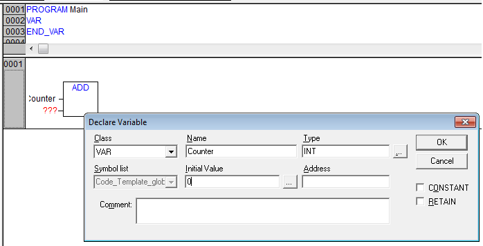
5. Create a variable by writing Counter to first input of ADD block. Press ENTER to open Input Assistant. Define variable Type to INT and zero to Initial Value.
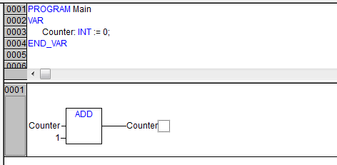
6. This program will increase the Counter value by 1 on each program cycle.
Add 1 to the second input of ADD block and assign the result back to Counter variable.
Assign can be found by right-clicking the network.

7. To check Epec unit's communication parameters:
-
open CANmoon
-
select used CAN adapter from drop-down menu (in this example Kvaser)
-
check that the bit rate is correct
-
click CAN bus button to go online
CANmoon checks heartbeat messages from the CAN bus and if one found, it checks all the needed information to show the unit in the CAN bus section.
Also, Scan button in CAN bus section triggers the scanning of the bus.
In this example, CANmoon finds a PLCopen node 126 (in CAN bus section, P means PLCopen).
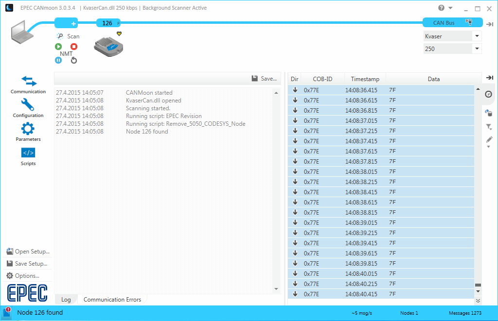
8. To download the CODESYS application, CODESYS communication node-ID is needed.
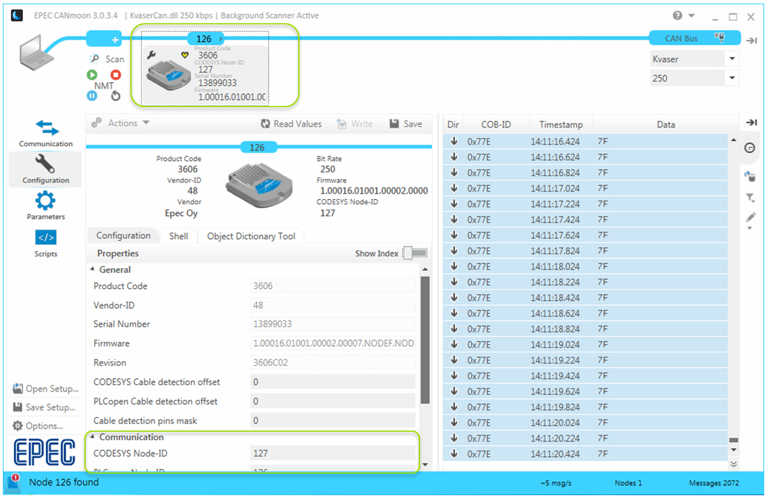
CODESYS node-ID can be checked from CAN bus section and also from Configuration view. To open Configuration, double-click the unit in CAN bus section. In this example, CODESYS communication node-ID is 127.
9. Go back to CODESYS and select Online > Communication Parameters.
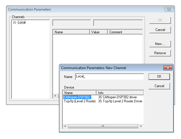
Create a new Channel by button New ... and select CANopen DSP302.
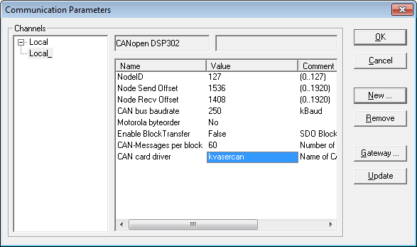
Set node-ID (127), baudrate (250) and CAN card driver (kvasercan).
Click OK.
10. To download the application, select Online > Login.
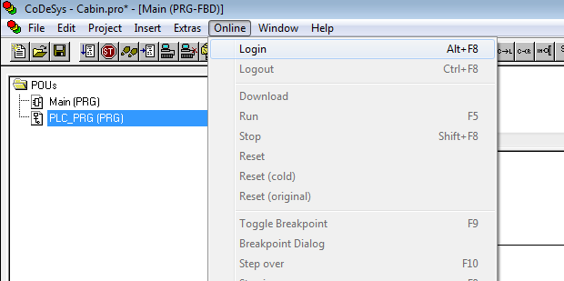
Select Yes

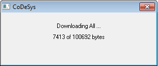
And CODESYS downloads the binary file.
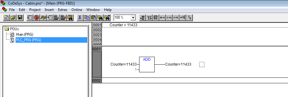
To run the application, press F5 or select Online > Run.



 icon from the hover menu.


