AI/DI_type091
Possible pin modes:
-
+10 V AI voltage mode
-
+20 mA AI current mode
-
DI mode
Select the mode using MultiTool Creator. MultiTool Creator generates the needed code using functions from SafeSSeriesIODriverExt library. For more information refer to Epec Programming and Libraries Manual and MultiTool Creator Manual.
AI (analog input) mode
-
Pins can be configured either as a current input or as a voltage input by a library function:
-
Voltage mode: High impedance input for signal from 0 to 10 V
-
Current mode: Low impedance input for signal from 0 to 22 mA
-
Pins can be used as e.g. joystick connection when the voltage mode is selected
|
|
When configured to current mode, the analog inputs are protected against prolonged overcurrent by using SafeSSeriesHardware programming library's function S_AIOverCurrentProtection. For more information, refer to Epec Programming and Libraries Manual.
|
DI (digital input) mode
-
These pins can also be used as digital inputs by using an application library
-
The pin must be configured to voltage mode when using as digital input
Electrical characteristics
|
Symbol |
Parameter |
Conditions |
Min |
Max |
Units |
|
VI |
Input Voltage measuring range |
|
0 |
10,5 |
V |
|
RI |
Input Resistance |
Voltage mode (referenced to GND) |
typ. 80 |
kΩ |
|
|
RSHUNT |
Input Resistance |
Current mode |
typ. 220 |
Ω |
|
|
II |
Input Current measuring range |
|
0 |
22,7 |
mA |
|
IE |
Full scale Input Error |
Voltage mode |
|
+/- 2 |
% |
|
Current mode |
|
+/- 2 |
% |
||
|
BW |
First-order low pass filter cut-off frequency (-3 dB) |
Voltage mode |
typ. 2200 |
Hz |
|
|
Current mode |
typ. 1200 |
Hz |
|||
|
CI |
Input pin capacitance |
|
typ. 10 |
nF |
|
|
VI-range |
Input voltage range |
(Note 1) |
-0,5 |
34 |
V |
|
|
Cable length |
|
|
30 |
m |
Note 1: Exceeding the max value might cause damage to input.
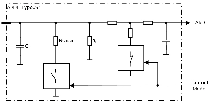
Functional block diagram