![]()
Configure the pin to current mode before applying the current signal.
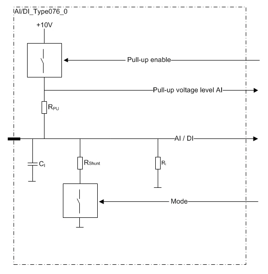
This type of pin is an analog input and a digital input
The configurable features are controlled by two control signals:
One control signal is for selecting:
Voltage mode: High impedance input for signal from 0 to 10V with or without pull-up.
Current mode: Low impedance input for signal from 0 to 22mA.
One control signal is for selecting (when in voltage mode):
Pull-up mode to +10V by a resistor
Pull-up mode to GND by a resistor
|
|
Configure the pin to current mode before applying the current signal. |
|
|
When measuring current (mA), the sensor connected to 5050 unit’s AI/DI pin must not be powered up before the 5050 control unit is operational. Otherwise the sensor’s input signal is not received correctly. |
|
|
When configured to current mode, analog inputs can be protected against overvoltage by using function AI_InputProtection in 5050int programming library. For more information, refer to Epec Programming and Libraries Manual. |
Electrical characteristics
|
Symbol |
Parameter |
Conditions |
Min |
Max |
Units |
|
VI |
Input Voltage measuring range |
Voltage mode |
0,0 |
10,0 |
V |
|
VPU |
Pull-up voltage |
(Note 1) |
typ. 10 |
V |
|
|
VI-PU |
Pull-up Voltage measuring range |
Voltage mode |
0,0 |
10,0 |
V |
|
II |
Input Current measuring range |
Current mode |
0,0 |
22,7 |
mA |
|
RI |
Input Resistance |
Voltage mode (Note 2) |
typ. 47,5 |
kΩ |
|
|
Current mode (Note 2) |
typ. 220 |
Ω |
|||
|
RPU |
Pull-up Resistance |
|
typ. 2,2 |
kΩ |
|
|
tI |
Time Constant of Input Low Pass Filter |
Voltage mode |
typ. 0,78 |
ms |
|
|
Current mode |
typ. 1,55 |
ms |
|||
|
tI-pull-up |
Time Constant of Pull-up Low Pass Filter |
Pull-up voltage measuring |
typ. 0,78 |
ms |
|
|
VI-prop |
Input Measuring accuracy Proportional factor |
Calculated (Note 4) |
|
+/-1 |
% |
|
VI-prop-PU |
Pull-up Voltage Measuring accuracy Proportional factor |
Calculated (Note 4) |
|
+/-1 |
% |
|
VI-zero |
Offset Error |
Voltage mode Calculated (Note 4) |
|
+/- 0,1 |
% |
|
|
+/-10 |
mV |
|||
|
Current mode Calculated (Note 4) |
|
+/-0,022 |
mA |
||
|
CI |
Input pin capacitance |
|
typ. 1 |
nF |
|
|
VI-max |
Max Input voltage |
Voltage mode Overload conditions (Note 3) |
-5 |
50 |
V |
|
Current mode Overload conditions (Note 3) |
-5 |
15 |
V |
||
Note 1: Temperature-dependent.
Note 2: Referenced to GND.
Note 3: Exceeding the max value might cause damage to input.
Note 4: Calculated theoretical maximum values based on component tolerances.
|
|
Refer to section Connection Examples to see examples of how to connect external actuators or sensors when using this type of pin. |