![]()
Generally, cabling should be properly designed and documented to help the initial assembly and maintenance.
It is highly recommended to mark each cable on both ends to avoid confusion and errors.
|
|
Generally, cabling should be properly designed and documented to help the initial assembly and maintenance. It is highly recommended to mark each cable on both ends to avoid confusion and errors.
|
|
|
The cables must be run in a safe route along the machine frame. When routing cables, avoid interfering objects and pay particular attention to moving parts of the machine. It is also good to minimize the amount of the connection points of the cable harness to maximize reliability. Also, all valid safety instructions should be observed when coupling.
|
The control units are connected with each other using standardized CAN bus.
The idea of the Epec embedded control system, is that all the control units are installed close to sensors, encoders and other equipment connected to them.
This way the amount of the traffic on the CAN bus is minimized and connections can be made using short wires.
Generally, the bus cable is terminated at both ends with termination resistors (ISO 11898:1993).
In Epec 5050, there are two different types to connect terminal resistor:
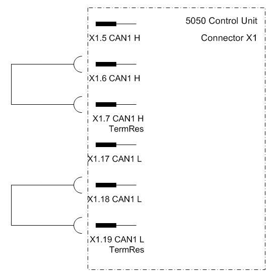
In CAN1, termination resistor can be connected internally as shown in the figure Example1 below
In all the CANs (CAN1, CAN2, CAN3 and CAN4), the termination resistor can be external
|
|
The cable lengths presented here are approximates. Actual cable lengths also depend on the cable quality, the cable type and also on the machine environment (possible interference). |

Example1. Termination resistor connection in CAN1

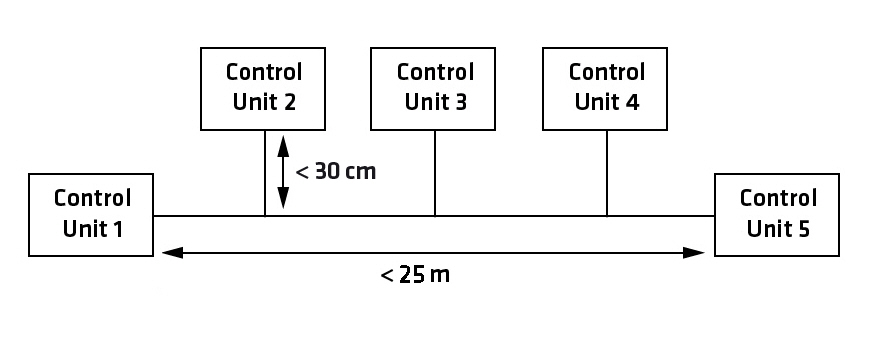
Example 2. Control system topology in theory with maximum bus speed (1000 kbit/s); Control Units in traditional bus arrangement. For more information about the bus speeds, refer to CiA DS-102 standard.

Example 3. Control system topology in theory with 250 kbit/s bus speed; Control Units in traditional bus arrangement. For more information about the bus speeds, refer to CiA DS-102 standard.

Example 4. The usage of the termination resistor (TR) in a conventional bus. The maximum recommended bus length is directly dependent on the bus speed.
In theory, the maximum length with the maximum speed can be up to 25 meters. If the bus speed is lower, the length can be extended.
The maximum length of the bus depends on the bus speed. For more information about the bus speeds, see the table below / refer to CiA DS-102 standard.
The following table shows some baud rates in general purpose CAN bus networks as well as the maximum bus length for a given baud rate, that CAN in Automation (CiA) international users and manufacturers group has recommended to be used. For more information, refer to CiA DS-102 standard.
CAN bus baud rates and bus lengths according to CiA DS-102 standard
|
Baudrate |
Bus length |
|
1 Mbits/s |
25 m |
|
800 kbits/s |
50 m |
|
500 kbits/s |
100 m |
|
250 kbits/s |
250 m |
|
125 kbits/s |
500 m |
|
50 kbits/s |
1000 m |