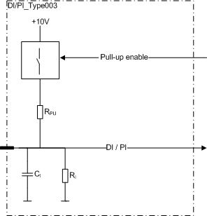
This type of pin is a ground referenced input (DI) including a pulse counting (PI) feature.
Pulse inputs can be used as a 1 or 2 channel pulse counter and they have a reset possibility. Possible software channels and pairs are listed in section SW channels for Pulse Inputs.
The configurable features are controlled by a control signal:
pull-up enable selection
When the pull-up to internal +10V is enabled, it controls two input pins as one. The pairs are indicated with lower case characters in the pin table's Group column in section Pinout Map.
Electrical characteristics
|
Symbol |
Parameter |
Conditions |
Min |
Max |
Units |
|
RI |
Input Resistance |
Referenced to GND (Note 1) |
typ. 12,4 |
kΩ |
|
|
RPU |
Pull-up Resistance |
Referenced to +10V (Note 2) |
typ. 2,2 |
kΩ |
|
|
VLevel |
Output voltage |
Unconnected pin, +10_PU enabled (Note 2) |
typ. 8,3 |
V |
|
|
VIH |
Input High Voltage level |
(Note 3) |
6,2 |
50 |
V |
|
VIL |
Input Low Voltage level |
|
0,0 |
4,1 |
V |
|
VI-max |
Max Input voltage |
(Note 6) |
-5 |
60 |
V |
|
fI |
Input Frequency |
tC= 4ms (Note 4,5,9)
|
|
250 |
Hz |
|
Input Frequency |
(Note 7,8,10) |
5 |
20000 |
Hz |
|
|
tI |
Input Pulse Width (pulse counting) |
(Note 7) |
0,025 |
250 |
ms |
|
CI |
Input pin capacitance |
|
typ. 1 |
nF |
|
Note 1: A pull-up resistor is not selected.
Note 2:When pull-up resistor is selected.
Note 3: Exceeding the max values might cause damage to input.
Note 4: These parameters depend on software cycle time.
Note 5: Applies to inputs used as normal digital input. Violating this rating may lead to application program not noticing all input state transitions.
Note 6: Overload conditions
Note 7: Violating this rating may lead to system not recognizing all input state transitions.
Note 8: It is possible to configure a smaller minimum frequency for some of the pins, see I/O table (Information column) in section I/O List.
Note 9: tC denotes software cycle time.
Note10: Max value can be reached by 2-98% pulse ration.
|
|
Refer to section Connection Examples to see examples of how to connect external actuators or sensors when using this type of pin. |