This is an internally regulated and monitored reference voltage supply for external devices.
This reference output can be switched on/off by application.
Overcurrent
External voltage protection
Errors are indicated with a fault signal
The level of the output voltage can be monitored by application.
Electrical characteristics
|
Symbol |
Parameter |
Conditions |
Min |
Max |
Units |
|
Vo-level |
Output voltage |
Output On; Unconnected pins |
typ. 5 |
V |
|
|
Ro |
Output Resistance |
Output On |
|
0,46 |
Ω |
|
Io |
Nominal Output Current |
Output On; Max total for all pins together |
0 |
270 |
mA |
|
Io-lim |
Internal Current Limitation |
Output On (Note 2, 3) |
typ. 370 |
mA |
|
|
Io-sc |
Short-circuit Current Limit |
Output On; Overcurrent |
typ. 270 |
mA |
|
|
Co |
Output Capacitance |
|
typ. 4,7 |
uF |
|
|
VI-max |
Max Input voltage |
Overload conditions (Note 1) |
|
33 |
V |
|
Voltage monitoring |
|||||
|
VI-range |
Nominal Voltage measuring range |
|
0 |
5 |
V |
|
|
Fault-signal overvoltage threshold |
Overvoltage |
Typ. 5,2 |
V |
|
|
|
Fault-signal activation time
|
Overvoltage / Overload |
|
10 |
ms |
Note 1: When output voltage is under overload conditions, for example, short circuit to supply voltages. Exceeding the max value might cause damage to output.
Note 2: Current limit for overcurrent protection to limit internal power dissipation.
Note 3: When the limit is exceeded, the output current is regulated. In regulation, the output is switched into overcurrent mode.
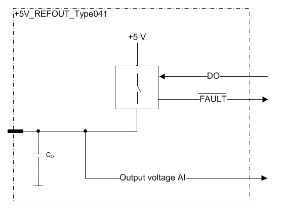
Functional block diagram
The +5V reference supply has two diagnostics checks:
analog output voltage monitoring and
dedicated digital fault-signal
Both can be used to indicate overload and overvoltage situations. The diagnostics are independent from each other.
|
|
For fastest and most reliable error detection, it is recommended to use both output voltage monitoring and fault-flag diagnostics to detect errors.
|
The diagnostics can detect overcurrent situation. The fault-signal is activated when excessive current is taken from the output. The output current is regulated when internal current limit is reached. The regulation current is always smaller than the limit. Current regulation causes the output voltage to drop with increasing load. This can be detected, using the output voltage monitoring feature, by setting a minimum (low) value limit for the output voltage.
With large enough loads, the output is switched temporarily off to protect the output from overheating. This is indicated by the fault-signal.
The fault-signal is deactivated, when the error source is removed by decreasing the load or when the output is turned off.
|
|
Overheat protection of the +5V REF can cause spurious errors in other analog measurements. Thus it is recommended to turn off the output when fault-signal becomes active.
|
Overvoltage event caused by an external source can be detected by using a combination of the diagnostic features. The fault-signal is activated when pin voltage goes above the fault-signal overvoltage threshold level. If the output voltage monitoring value is 5 V (or more) and the fault-signal is active, it can be determined that an external voltage source is connected to the output pin.
The output pins are protected against external voltages, but it is not recommended to connect external voltage sources to these pins.
|
|
In case of a limit violation, the output should be disabled as soon as possible. The control unit can handle short term errors, but long term (e.g. several hours) exposures should be avoided with application/system design. Long term exposure to overvoltage or overload can cause permanent damage to the unit.
|