![]()
When configured to current mode, analog inputs can be protected against overvoltage by using 3000AnalogInputProtection programming library. For more information, refer to Epec Programming and Libraries Manual.
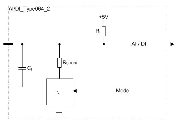
These pins are analog inputs
There is an internal 2,2 kΩ resistor connected to +5 V in the unit.
It provides appropriate measuring current for the external sensor. Any resistive sensor with reasonable resistance range can be used.
The pins can be configured either as a current input or as a voltage input.
There is a control signal for selecting:
Voltage mode: High impedance input for signal from 0 to 5 V
Current mode: Low impedance input for signal from 0 to 22 mA
The input impedance of each pin is controlled by a bit in output memory (%Q)
|
|
When configured to current mode, analog inputs can be protected against overvoltage by using 3000AnalogInputProtection programming library. For more information, refer to Epec Programming and Libraries Manual.
|
These pins can also be used as digital inputs by using an application library.
The pin must be configured to voltage mode when using as digital input
Electrical characteristics
|
Symbol |
Parameter |
Conditions |
Min |
Max |
Units |
|
VI |
Input Voltage measuring range |
|
0 |
5 |
V |
|
RI |
Input Resistance |
Voltage mode (referenced to +5 V) |
typ. 2,2 ±1% |
kΩ |
|
|
Current mode |
typ. 220 |
Ω |
|||
|
II |
Input Current measuring range |
|
0 |
22,7 |
mA |
|
IE |
Input Error |
Voltage mode |
|
0,18 |
V |
|
Current mode |
|
0,8 |
mA |
||
|
BW |
Input Low Pass Filter Bandwidth |
-3 dB cut-off frequency |
typ.40 |
Hz |
|
|
CI |
Input pin capacitance |
|
typ. 47 |
nF |
|
|
VI-range |
Input voltage range |
Voltage mode (Note 1) |
-0,5 |
33 |
V |
|
Current mode (Note 1) |
-0,5 |
30 |
V |
||
Note 1: Exceeding the max value might cause damage to input.
Functional block diagram