![]()
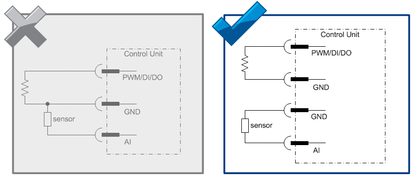
Closed circuit loops are always recommended and mandatory when you are using DO or PWM pin as an input.
Closed circuit loop means that the current from the control unit to the sensor must return to the same control unit, see the figures below.
|
Closed circuit loops are always recommended and mandatory when you are using DO or PWM pin as an input. Closed circuit loop means that the current from the control unit to the sensor must return to the same control unit, see the figures below. |
|
To ensure correct measurement, reserve separate GND pin(s) for AI pin(s) and don't use it/them for any other purposes. See cabling example below. |
The cabling for encoders etc. is in many cases supplied together with them.
In many cases, very simple basic cable may be used, e.g. automobile R2 cable (0,5 or 1,0) by NK Cables.
Dimensions of the cable should be appropriate for AMP contacts (so that crimping is possible).
Refer to AMPSEAL table (in section Accessories and Ordering Codes) for dimensions.
Take extra care for protecting the cables against physical wear and damage.
Only one wire can be connected to one AMPSEAL connector pin. However, if more than one wire has to be connected to one connector pin, it has to be connected by branch wiring.
Some voltage inputs use relatively low voltages.
Consider using shielded cables for these encoders etc. especially for longer distances to increase safety
Using shielded cable is recommended also in joystick connections.
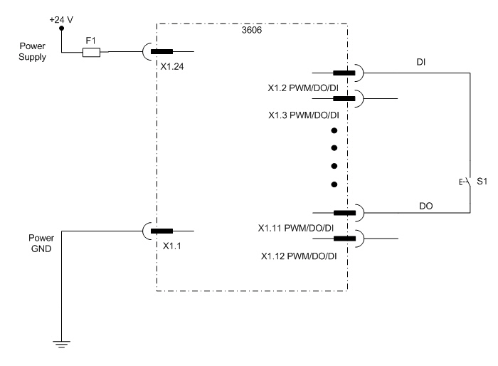
The following figure describes the closed loop wiring:
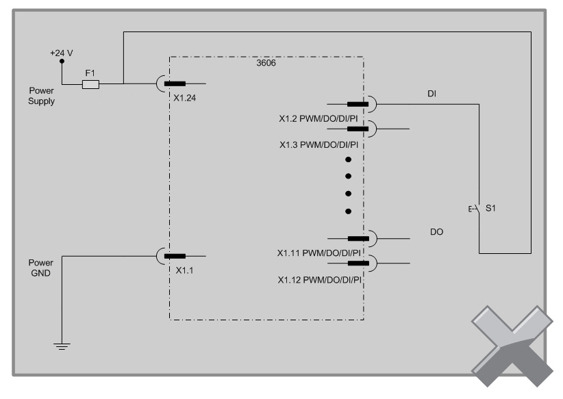
Do not connect the closed circuit loop as shown in the following figure:
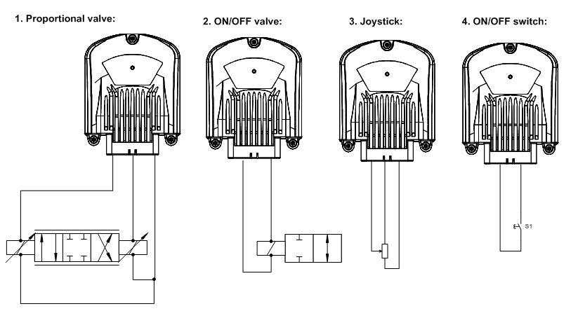
The following figure describes four different ways to connect closed circuit loop through the control unit:
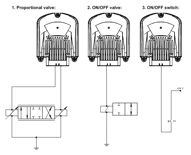
The following figure describes three different ways to connect open circuit loop (from the control unit’s point of view):
AI - GND cabling examples (use separate GND pin for AI pins):
All sensors and encoders must be wired according to the closed-loop principle, i.e. the power for the sensors and encoders is supplied by the control unit they are connected to. This way, it is possible to avoid potential harmful differences, so the MOSFET driven output power switching operates properly.
When designing the sensor and encoder connections, observe single-point grounding. Each control unit connector has several GND pins which should be used.
Refer to section Power Supply for accurate pin allocation of connectors.