![]()
The CAN bus cable is the neural backbone of the whole system and should be designed and constructed with extra care.
|
The CAN bus cable is the neural backbone of the whole system and should be designed and constructed with extra care. |
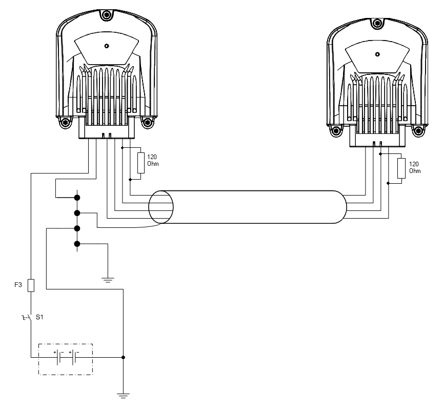
The control unit's CAN1 is equipped with double pins that enables cabling without branching the wire harness
For information about the CAN bus lengths and baud rates, refer to section System Topologies.
Cable
It is recommended to use high quality and twisted (approx. 1 round / 1 inch) CAN bus cable.
Normal UTP (Unshielded Twisted Pairs) cable is well suited for distances under approximately 10 meters.
In longer distances, and especially if there is possibility for electromagnetic interference, it is highly recommended to use shielded and twisted cable for CAN bus, also for shorter distances.
To avoid electromagnetic interference (EMI), locate the bus cable as far away from high-current carrying cables as possible. Generally, the amount of the connections and connectors should be minimized to maximize security; also all connections should be done carefully.
The shield grounding must be done only in one end of the cable
Cable shield
Connection example when there is a GND pin available in the control unit:

Connection example when there is not a GND pin available in the control unit:
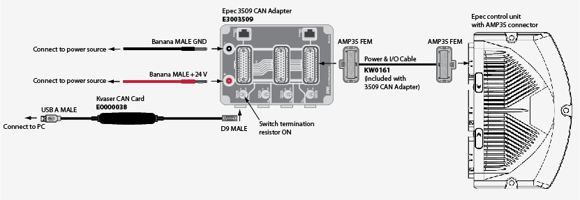
The following figure describes cabling for CAN communication between Epec control units and a PC.
Ordering codes for the needed hardware are included in the figure.
Epec control units with AMP35 connector, example 1:
Epec control units with AMP35 connector, example 2:
|
An external termination resistor (120 Ω) has to be connected at both ends between CAN H and CAN L. |
