CAN Interface
The physical interface of CAN interface is according to ISO 11898 and CAN 2.0B protocol
The downloading of the configuration can only be done via CAN1
CAN1 interface supports bit rates 250, 500 and 1000 kbit/s (selected by cable)
X3.13 (BAUD1) |
X2.25 (BAUD2) |
Bit rate kbit/s |
- |
- |
500 |
GND |
- |
250 |
- |
GND |
1000 |
GND |
GND |
Reserved |
(- = No connection, GND = pin connected to ground)
CAN2 interface supports bit rates 50, 125, 250, 500, 800 and 1000 kbit/s (selected by Object Dictionary)
CAN1 and CAN2 are CANopen compatible
11-bit and 29-bit message receive and transmit are supported.
CANopen NODE ID:
CANopen Node ID is selected by four pins (16 selectable ID's). The value range is 0x50 - 0x5F. The selected addition is added to the base value, which is 0x50. It is binary coded according to the following table:
X2.24 (NODE ID 4) |
X2.23 (NODE ID 3) |
X2.22 (NODE ID 2) |
X2.21 (NODE ID1) |
ID |
- |
- |
- |
- |
0x50 |
- |
- |
- |
GND |
0x51 |
- |
- |
GND |
- |
0x52 |
- |
- |
GND |
GND |
0x53 |
- |
GND |
- |
- |
0x54 |
- |
GND |
- |
GND |
0x55 |
- |
GND |
GND |
- |
0x56 |
- |
GND |
GND |
GND |
0x57 |
GND |
- |
- |
- |
0x58 |
GND |
- |
- |
GND |
0x59 |
GND |
- |
GND |
- |
0x5A |
GND |
- |
GND |
GND |
0x5B |
GND |
GND |
- |
- |
0x5C |
GND |
GND |
- |
GND |
0x5D |
GND |
GND |
GND |
- |
0x5E |
GND |
GND |
GND |
GND |
0x5F |
CAN Bus Connection Pins
The CAN communication pins are connected in the control unit’s LEAVYSEAL-21 connector as follows:
Designation |
Pin number |
CAN1 interface, system interface |
X3.20 (CAN H) X3.21 (CAN H) X3.17 (CAN L) X3.18 (CAN L) X3.14 (CAN L terminator) |
CAN2 interface |
X3.19 (CAN H) X3.16 (CAN L)
|
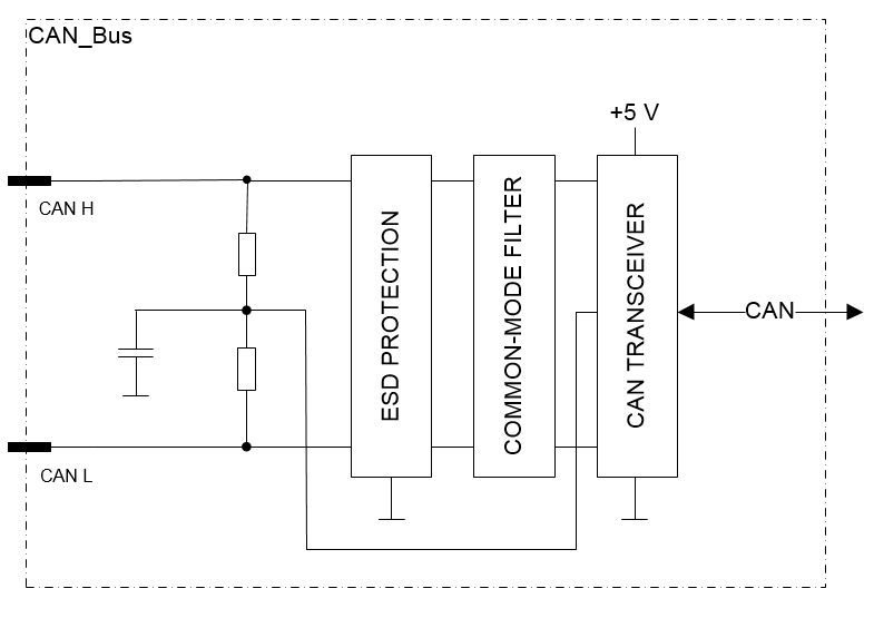
Functional block diagram