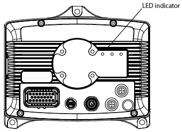
The LED indicator is situated on the connector side of the unit according tot he following figure:
|
Some of the states must be implemented by using EXT programming library. For more information about EXT programming library, refer to Epec programming and libraries manual. |
The LED has green and red indicators and they indicate different operating conditions according to the following table:
LED State |
LED 1 |
Implemented in device firmware or hardware |
Implement by using in device CODESYS runtime or code template |
Explanation |
OFF |
- |
X |
|
No supply voltage |
Power ON |
Red LED is constantly ON |
X |
|
Supply voltage is on, software is not running. |
Boot-up |
Yellow LED is constantly ON |
X |
|
There is no application or runtime. ApplicationLoader has nothing to start-up. |
CODESYS runtime status |
Green LED is constantly ON |
|
X |
CODESYS application stopped or update is in progress |
CODESYS application status |
Green LED blinks 2 times/second |
|
X |
CODESYS application running and SystemOk TRUE |
CODESYS application status |
Red LED blinks 2 times/second |
X |
CODESYS application running and SystemOk FALSE |
|
No CODESYS Application |
Green LED blinks 5 times/second |
|
X |
CODESYS runtime is running, no PLCopen application |
Rescue |
Blue LED constantly ON |
X |
|
Rescue is initializing |
Firmware update |
Red/Green LEDs blink alternately |
X |
|
Firmware update in progress |
ApplicationException |
Red LED constantly ON |
X |
|
Application exception, for example, division by zero. |