![]()
Pins 1.14, 1,15, 1.25,1.26 have optimized PT1000 sensor support. When using with PT1000, select range 0-2,5 V for the pin (with Epec MultiTool).
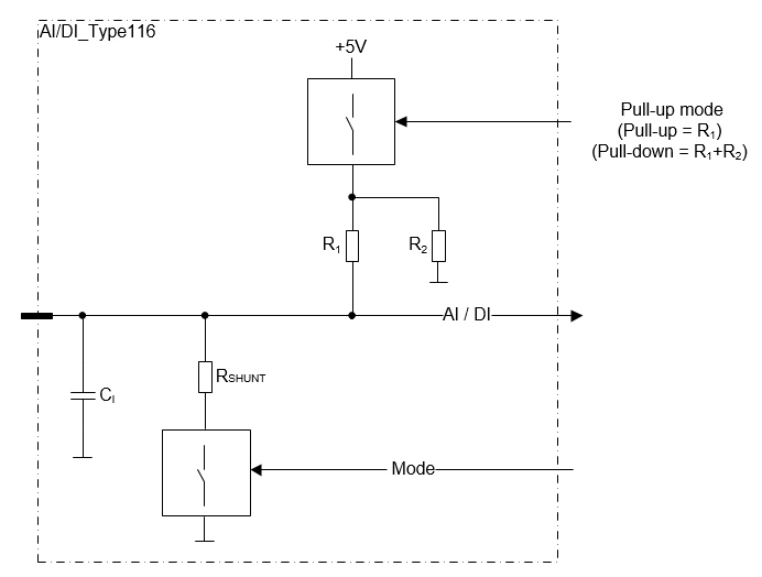
These pins are analog inputs
The configurable features are controlled by two control signals:
One control signal is for selecting:
Voltage mode: High impedance input for signal from 0 to 5 V with or without pull-up.
Current mode: Low impedance input for signal from 0 to 22 mA.
One control signal is for selecting (when in voltage mode):
Pull-up mode to +5 V by a resistor
Pull-down mode to GND by a resistor
The input impedance of each pin when using current mode is controlled by a bit in output memory (%Q)
|
Pins 1.14, 1,15, 1.25,1.26 have optimized PT1000 sensor support. When using with PT1000, select range 0-2,5 V for the pin (with Epec MultiTool).
|
|
When configured to current mode, analog inputs can be protected against overvoltage by using 3000AnalogInputProtection programming library. For more information, refer to Epec Programming and Libraries Manual.
|
These pins can also be used as digital inputs by using an application library.
The pin must be configured to voltage mode when using as digital input
Electrical characteristics
Symbol |
Parameter |
Conditions |
Min |
Max |
Units |
VI |
Input Voltage measuring range |
|
0 |
5 |
V |
RI |
Input Resistance |
Pull-up voltage mode (referenced to +5 V) |
typ. 2,2 |
kΩ |
|
Pull-down voltage mode (referenced to GND) |
typ. 84,2 |
kΩ |
|||
Current mode |
typ. 220 |
Ω |
|||
II |
Input Current measuring range |
|
0 |
22,7 |
mA |
IE |
Input Error |
Voltage mode |
|
0,18 |
V |
Current mode |
|
0,8 |
mA |
||
BW |
Input Low Pass Filter Bandwidth |
-3 dB cut-off frequency |
typ.41 |
Hz |
|
CI |
Input pin capacitance |
|
typ. 47 |
nF |
|
VI-range |
Input voltage range |
Voltage mode (Note 1) |
-0,5 |
33 |
V |
Current mode (Note 1) |
-0,5 |
15 |
V |
||
Note 1: Exceeding the max value might cause damage to input.