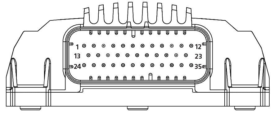
The connector is placed in the control unit according to the following figure:
The following table lists the pins according their pin number. Other columns offer quick information about the pin and links for more information.
Pin number |
Pin type |
Details |
Current / Voltage |
Description |
First row: |
||||
X1.1 |
GND |
|
|
Supply GND connection |
X1.2 |
|
|||
X1.3 |
|
|||
X1.4 |
PI/DI _Type039_0_2 |
|
|
|
X1.5 |
CAN1H |
|
|
|
X1.6 |
CAN1H |
|
|
|
X1.7 |
|
|||
X1.8 |
|
|||
X1.9 |
|
|||
X1.10 |
|
|||
X1.11 |
|
|||
X1.12 |
|
|||
Second row: |
||||
X1.13 |
LOADER BSL |
For factory use only |
|
|
X1.14 |
||||
X1.15 |
||||
X1.16 |
GND |
|
|
|
X1.17 |
CAN1L |
|
|
|
X1.18 |
CAN1L |
|
|
|
X1.19 |
CAN1L_Terminator |
|
|
|
X1.20 |
||||
X1.21 |
||||
X1.22 |
||||
X1.23 |
||||
Third row: |
||||
X1.24 |
|
|
Supply connection |
|
X1.25 |
||||
X1.26 |
||||
X1.27 |
||||
X1.28 |
Logic Supply | |||
X1.29 |
||||
X1.30 |
GND |
|
|
|
X1.31 |
||||
X1.32 |
||||
X1.33 |
GND |
|
|
|
X1.34 |
||||
X1.35 |
||||