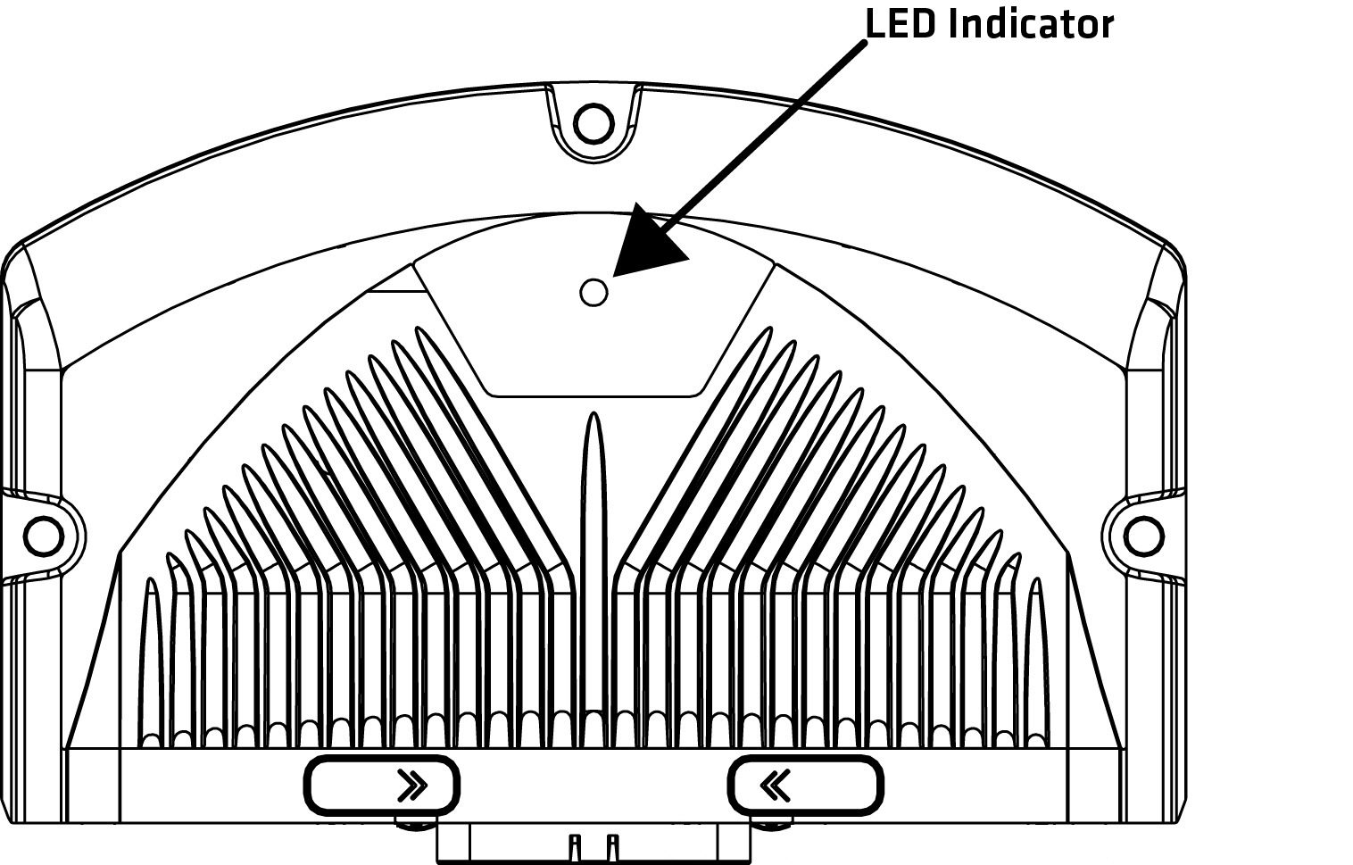
The LED indicator light is situated on the top side of the unit according to the following figure:
|
Some of the states must be implemented to application by using EXT programming library. For more information about EXT programming library, refer to Epec Programming and Libraries Manual. |
Green, blue and red LED indicate different operating conditions according to the following table:
State |
Green LED |
Red LED |
Blue LED |
Implemented by |
Explanation |
Power off |
- |
- |
- |
- |
No supply voltage |
Power on and no SW running |
- |
ON |
- |
HW |
Supply voltage is on, software is not running. |
Power on and SW at init phase with no errors |
ON |
- |
- |
Boot/Firmware |
Boot/Firmware is at init phase. |
No application |
5 Hz |
- |
- |
Firmware |
Firmware is running, no PLCopen application |
Application stopped |
ON |
- |
- |
Firmware |
Application is stopped. |
Fatal error |
- |
ON |
- |
Boot/Firmware/HW |
Control unit boot-up failed or a critical error while running. |
Update |
Blinks alternately with red LED |
Blinks alternately with green LED |
- |
Boot |
After firmware update boot-up, during the installation phase, red and green LEDs are flashed alternately. |
Application init |
ON |
- |
- |
Application |
LED is continuously on also during the initialization: starting from power on until the application is running and the I/O / CAN initializations are done. |
ApplicationOk + No Safe Operational |
- |
-
|
2 Hz
|
Application |
Application is running and the system is OK and in safe state (safety switches are open - no voltage is provided to outputs) |
ApplicationOk + Safe Operational |
2 Hz |
- |
- |
Application |
Application is running and the system is OK and in safe operational state (safety switches are closed) |
Application Error (system not OK) |
- |
2 Hz |
- |
Application |
Application error. The system is not OK. |
Application custom control |
Application specific |
Application specific |
Application specific |
Application |
Application can override code template's LED control by application specific implementation |