Possible pin modes:
+5 V AI mode
DI mode
PI mode
Select the mode using MultiTool. MultiTool generates the needed code using functions from SafeSSeriesIODriverExt library. For more information refer to Epec Programming and Libraries Manual and MultiTool Manual.
AI (analog input) mode
These pins have a pull-up/pull-down selection by a library function
Pins can be used as high impedance voltage inputs for signals from 0 to 5 volts
Pins can be used as e.g. joystick connection when AI mode without pull-up/pull-down is selected
Pins can be used as e.g. resistive temperature sensor connection when AI mode with pull-up is selected
DI (digital input) mode
These pins can be used as digital inputs by using an application library
The pin must be configured to DI mode when using it as a digital input. This enables a pull-down resistor to the ground
PI (pulse input) mode
This input mode has a pulse counting (PI), pulse width measuring, pulse frequency and pulse ratio features
These pins have a pull-up/pull-down selection by a library function
Pulse input mode can be used as a 1 or 2 channel pulse counter
1 channel pulse counter, it is possible to use a specific pin as reset channel
2 channel pulse counter, the reset feature is done by software. Refer to section Programming SC52 Safety Control Units > I/O Programming > AI/DI/PI_type096
Possible software channels and pairs are listed in section I/O List and in Epec Programming and Libraries Manual, section Programming SC52 Safety Control Units > I/O Programming > AI/DI/PI_type096
This mode is also suitable for quadrature sensor position counting
Electrical characteristics
Symbol |
Parameter |
Conditions |
Min |
Max |
Units |
VI |
Input Voltage measuring range |
0 |
6 |
V |
|
RI |
Input Resistance |
Voltage mode Referenced to GND |
typ. 80,5 |
kΩ |
|
RPD |
Pull-down Resistance |
DI mode |
typ. 10 |
kΩ |
|
RPU |
Pull-up Resistance |
|
2,18 |
2,22 |
kΩ |
IE |
Input Error |
Voltage mode |
|
+/- 2 |
% |
BW |
Input Low Pass Filter Bandwidth (-3 dB cut-off frequency) |
Voltage mode |
1600 |
Hz |
|
VIH |
Input High Voltage |
PI mode |
3,6 |
34 |
V |
VIL |
Input Low Voltage |
PI mode |
-0,5 |
1,4 |
V |
fI |
Input Frequency (frequency measurement and pulse counting) |
(Note 4) |
|
20 |
kHz |
fI |
Input Frequency |
(Note 2, 3) |
|
1/ 2tC |
kHz |
tI |
Input Pulse Width |
|
0,1 |
500 |
ms |
CI |
Input Capacitance |
|
typ. 1 |
nF |
|
VI-range
|
Input voltage range
|
(Note 1) |
-0,5 |
34 |
V |
|
Cable length
|
|
|
30 |
m |
Note 1: Exceeding the max value might cause damage to input.
Note 2: tC denotes the software cycle time in milliseconds.
Note 3: The pulse width must be greater that the software cycle time. For example with 50/50 pulse ratio, the pulse frequency is 1 / (2*pulse width)
Note 4: The maximum value can be reached with 50 % duty cycle
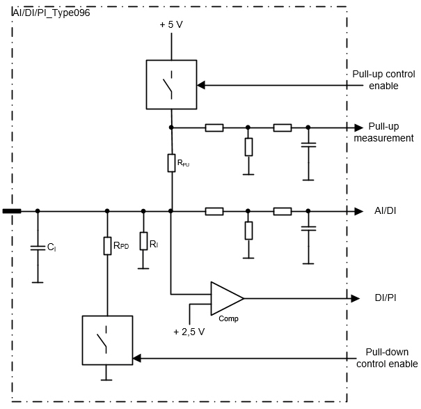
Functional block diagram