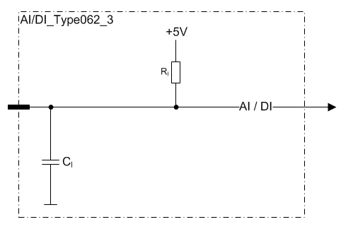
These pins are analog inputs
There is an internal 330 Ω resistor connected to +5 V in the unit.
It provides appropriate measuring current for the external sensor. Any resistive sensor with reasonable resistance range can be used.
The input impedance of each pin is controlled by a bit in output memory (%Q)
These pins can also be used as digital inputs by using an application library.
Electrical characteristics
|
Symbol |
Parameter |
Conditions |
Min |
Max |
Units |
|
VI |
Input Voltage measuring range |
|
0 |
5 |
V |
|
RI |
Input Resistance |
Voltage mode (referenced to +5 V) |
typ. 330 |
Ω |
|
|
IE |
Input Error |
Voltage mode |
|
0,18 |
V |
|
BW |
Input Low Pass Filter Bandwidth |
-3 dB cut-off frequency |
typ.100 |
Hz |
|
|
CI |
Input pin capacitance |
|
typ. 1 |
nF |
|
|
VI-range |
Input voltage range |
Voltage mode (Note 1) |
-0,5 |
33 |
V |
Note 1: Exceeding the max value might cause damage to input.
Functional block diagram