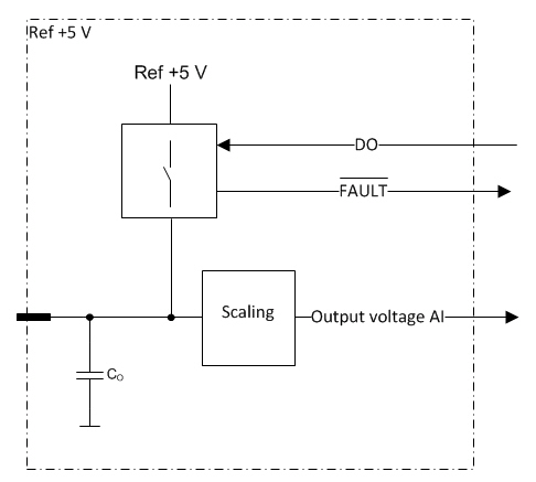
This is an internally regulated and monitored reference voltage supply for external devices.
This reference output can be switched on/off by application.
Overcurrent
External voltage protection
Errors are indicated with a fault signal
The level of the output voltage can be monitored by application.
Electrical characteristics
|
Symbol |
Parameter |
Conditions |
Min |
Max |
Units |
|
Vo-level |
Output voltage |
Output On; Unconnected pins |
typ. 5 |
V |
|
|
Ro |
Output Resistance |
Output On |
|
2 |
Ω |
|
Io |
Nominal Output Current |
Output On; |
0 |
100 |
mA |
|
Io-lim |
Internal Current Limitation |
Output On (Note 2, 3) |
typ. 500 |
mA |
|
|
Io-sc |
Short-circuit Current Limit |
Output On; Overcurrent, RL = 0 |
typ. 350 |
mA |
|
|
Co |
Output Capacitance |
|
typ. 47 |
uF |
|
|
|
Fault-signal overvoltage threshold level |
External overvoltage conditions |
typ. 5,7 |
V |
|
|
VI-max |
Max Input voltage |
Overload conditions (Note 1) |
0 |
36 |
V |
|
Voltage monitoring |
|||||
|
VI |
Nominal Voltage measuring range |
|
0 |
7 |
V |
|
|
Scaling Factor |
(Note 4) |
typ. 0,5 |
V/V |
|
Note 1: When output voltage is under overload conditions, for example, short circuit to supply voltages. Exceeding the max value might cause damage to output.
Note 2: Current limit for overcurrent protection to limit internal power dissipation.
Note 3: When the limit is exceeded, the output current is regulated. In regulation, the output is switched into overcurrent mode.
Note 4: The measurement is scaled down before the conversion. The effect is compensated in Epec software libraries. For more information, see Epec Programming and Libraries manual.
Functional block diagram