![]()
Closed circuit loops are mandatory when using this pin.
Closed circuit loop means that the current from the control unit to the sensor must return to the same control unit, see the figures in section I/O Cabling.
|
|
Closed circuit loops are mandatory when using this pin. Closed circuit loop means that the current from the control unit to the sensor must return to the same control unit, see the figures in section I/O Cabling. |
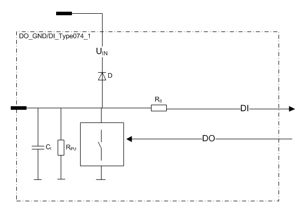
This type of pin is a current sinking output
In other words, this type of output connects the loads to the ground (GND) and simultaneously the state of the output can be monitored with an input.
|
It is recommended to use the function blocks in DigitalOutputDiagnostics library to protect and diagnose outputs when used as digital outputs. For more information, refer to Epec Programming and Libraries Manual. |
This type of pin can also be used as an input
In this case, the output functionality of the pin must be kept in the off state.
Electrical characteristics
|
Symbol |
Parameter |
Conditions |
Min |
Max |
Units |
|
RON |
On-resistance |
Output On |
|
50 |
mΩ |
|
II |
Nominal Input Current |
Output On, VDCLOAD < max VI-range |
0 |
4 |
A |
|
Digital status input |
|||||
|
RI |
Input Resistance |
Output Off |
|
kΩ |
|
|
VIH |
Digital status input |
Output Off (Note 2, 3) |
2,3 |
Uin |
V |
|
VIL |
Digital status input |
Output Off (Note 3) |
-0,5 |
1 |
V |
|
CI |
Input Capacitance |
|
typ. 1 |
nF |
|
Note 1: Parameter is defined by resistive load.
Note 2: Exceeding the limit values might cause damage to input.
Note 3: No hysteresis. State between voltages 1 V and 2,3 V is unknown.