![]()
For changing the pull-up resistor, see 4602Specific programming library in Epec Programming and Libraries Manual.
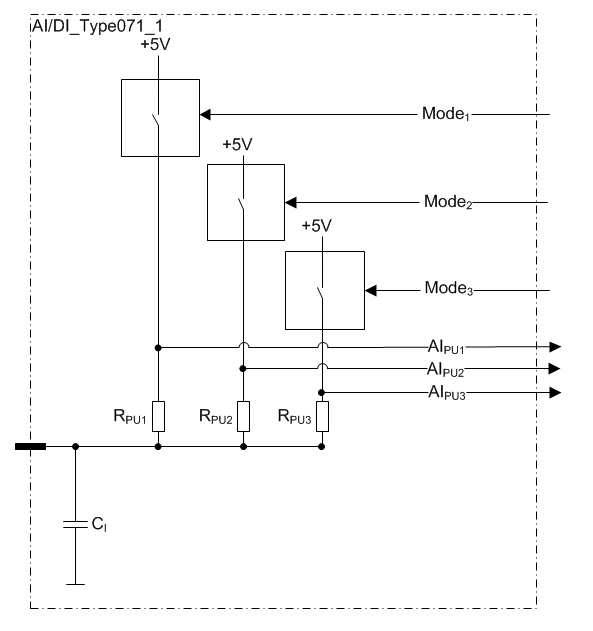
This type of pin is an analog input and a digital input
The configurable features are controlled by three control signals:
The pin can be connected to +5 V by one of three different sizes of pull-up resistors. The three selectable resistor sizes are described in the Electrical characteristics table.
|
|
For changing the pull-up resistor, see 4602Specific programming library in Epec Programming and Libraries Manual.
|
These pins can also be used as digital inputs by using an application library.
Electrical characteristics
|
Symbol |
Parameter |
Conditions |
Min |
Max |
Units |
|
VI |
Input Voltage measuring range |
Voltage mode |
0,0 |
5,0 |
V |
|
VPU |
Pull-up voltage |
(Note 1) |
typ. 5 |
V |
|
|
VI-PU |
Pull-up Voltage measuring range |
|
0,0 |
5,0 |
V |
|
RPU |
Pull-up Resistance |
Pull-up resistor 1 (Note 2) |
typ. 1,2 |
kΩ |
|
|
Pull-up resistor 2 (Note 2) |
typ. 4,87 |
kΩ |
|||
|
Pull-up resistor 3 (Note 2) |
typ. 47 |
kΩ |
|||
|
BW |
Input Low Pass Filter Bandwidth |
-3 dB cut-off frequency |
typ. 40 |
Hz |
|
|
BW-pull-up |
Input Low Pass Filter Bandwidth |
-3 dB cut-off frequency, Pull-up voltage measuring |
typ. 47 |
Hz |
|
|
IE |
Input Error |
Calculated (Note 4) |
|
± 2 |
% |
|
CI |
Input pin capacitance |
|
typ. 1 |
nF |
|
|
VI-max |
Max Input voltage |
Overload conditions (Note 3) |
-0,5 |
50 |
V |
Note 1: Temperature and load-dependent, measure using library SensorCalibrationAndDiagnostic. Use pull-up voltage measurement value as the sensor calibration's reference voltage (for more information see Epec Programming and Libraries Manual).
Note 2: Referenced to + 5 V.
Note 3: Exceeding the max value might cause damage to input.
Note 4: When using function ADC_To_Ohm in library ADConversion .