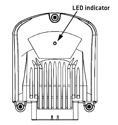
The LED indicator light is situated on the top side of the 3606 according to the following figure:
|
Some of the states must be implemented by using EXT programming library. For more information about EXT programming library, refer to Epec programming and libraries manual. |
The LED has green and red indicators and they indicate different operating conditions according to the following table:
LED State |
Green LED |
Red LED |
Implemented in device firmware |
Implement by using EXT programming library |
Explanation |
Off |
- |
- |
X |
|
No supply voltage or an application stop state after a watchdog reset. |
Default Application or No User Application |
Blinks 5 times/second |
- |
X |
|
Firmware is running, no PLCopen application or application download in progress |
ApplicationOk |
Blinks 2 times/ second |
- |
X |
|
Application is running and the system is OK |
Application Stopped or initializing |
LED is constantly on |
- |
X |
X |
Stopped / Starting / Initializing Firmware: LED is continuously on while application is stopped. EXT Library: LED is continuously on also during the initialization: starting from power on until the application is running and the I/O / CAN initializations are done. |
FatalError |
- |
LED is constantly on |
X |
|
Control unit boot-up failed or a critical firmware error while running. |
ApplicationError |
- |
Blinks 2 times/ second |
|
X |
External PLCopen library controls, for example when output controlling is disabled, so called safe state. |
IOError |
- |
Blinks 5 times/second |
|
X |
External PLCopen library controls, for example when system is OK but there is short circuit in one of the outputs or other similar error is active (depends of application) |
Update |
Blinks alternately with red LED |
Blinks alternately with green LED |
X |
|
After firmware update boot-up, during the installation phase, red and green LEDs are flashed alternately.
|