Create CODESYS project
To create a CODESYS project:
-
Right-click the unit and select Create CODESYS project or click  on the ribbon
-
MultiTool opens the CODESYS template project, imports the configurations to it and saves the project with a control unit name. Note that CODESYS tries to open the previously saved project and for this reason may show error dialogs. Error dialogs need to be acknowledged before importing can be done.
-
Add Main POU to the project in CODESYS.
-
Build and login.
For more information on creating a CODESYS project, refer to topics Quick Start Guide and Updating MultiTool Configurations to CODESYS Project.
|

|
Read-only files, such as libraries from version control, are not overwritten in System Export.
|
Vanhat kappaleet:
Code Template Structure
MultiTool Creator automatically creates a code template for CODESYS project when Create CODESYS Project is selected. The code template contains all variable definitions and initialization needed for programming the device.
This topic briefly introduces the code template parts:
The PLC_PRG is the main POU of a CODESYS project. MultiTool Creator automatically generates PLC_PRG for the CODESYS project and it will always be overwritten when changes done in MultiTool Creator are imported to the CODESYS project. For this reason, the user application code should never be added to PLC_PRG.
For the user application code, create a new POU called Main. This will be the entry point of the user application. The code template automatically calls the Main program in the PLC_PRG's action Application. It is not overwritten by MultiTool Creator. If the Main POU is missing from the application, the CODESYS build command gives an error. The code template in CODESYS 3.5 projects includes a Main POU that is made with ST language. To make the Main POU with another programming language, delete the Main POU and make a new one.
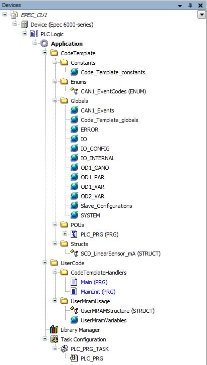
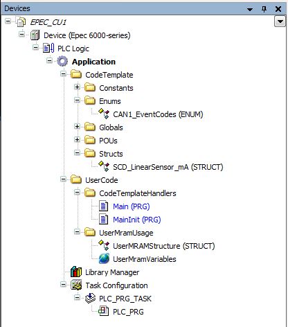
The CODESYS 3.5 Device tree in the following image includes all project objects on the same view:
CODESYS 2.3 code template is divided to the POUs, Data types and Resources tabs.
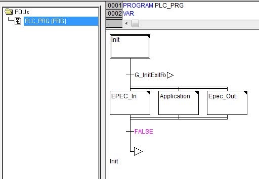
The PLC_PRG is divided into four actions: Init, Epec_In, Application and Epec_Out.
The Init action is run on each program cycle until all initializations are done. The initialization phase is divided into several steps to minimize the needed time of each program cycle. After the initialization phase, Epec_In, Application and Epec_Out actions are run on each program cycle.
|
PLC_PRGs action
|
Sub-action
|
Description
|
|
Init
|
Init_Entry
|
Reads system parameters
Contains call of the user POU
|
|
Init_Flash
|
Initializes non volatile memory
|
|
Init_IO
|
I/O initialization functions
|
|
Init_Bus
|
Initializes CANVXD library instance for each CAN
|
|
Init_Protocols_CANx (*)
|
CAN protocol initializations for each CAN bus, including CANopen and SAE J1939
|
|
Init_Events
|
Initializations for Events
|
|
Init_Exit
|
Initializes the identity object (1018h)
|
|
Epec_In
|
IO_Filter
|
Filters I/O pin raw values
|
|
Diag
|
CAN bus diagnostics
HWD_Diagnostic instance call
G_SystemOk variable handling
LED handling
|
|
Bus
|
Updates CAN buffers
|
|
Other
|
Reserved for future use
|
|
Application
|
Only contains call for the user application Main
|
|
Epec_Out
|
Other
|
All functions that are needed to run at the end of the program cycle, such as
- analogue input protection
- parameter saving
- resetting the control device if needed (NMT reset)
|
|
IOHandleOutputs(**)
|
Copies data from variables which are used in application for the IO to variables defined in description file. This copying sets actual IO to wanted state.
|
* CAN bus consecutive numbering, typically 1=CAN1, 2=CAN2 etc.
** only in CODESYS 3.5 version
(Implicit) Globals
MultiTool Creator generates global variable and function block instance definitions to (Implicit) Globals lists. These variables and instances can be used, for example, for diagnosing CAN bus and hardware. Code template calls these function blocks automatically. Code template global definitions can be found from
-
the Resources tab in CODESYS 2.3 or
-
the Device tree in CODESYS 3.5 (CodeTemplate > Globals)
Variable definitions are divided into several global lists, defined in the table below.
|
Global variable list
|
Description
|
|
Code_Template_constants(**)
|
Constant definitions
|
|
Code_Template_Globals
|
All variable definitions and function block instances needed in code template, such as init phase booleans
- CANopen instance and array definitions
Variables that might be needed in application, such as G_SystemOk boolean, HWD_Measurements instance and limit definitions.
|
|
ERRORS
|
Error variables
|
|
EVENTS
|
Event source addresses and data initialization.
|
|
IO
|
I/O pin variables that are needed when developing an application
|
|
IO_RAW
|
Non scaled raw values of I/O pins.
Not needed in normal use, since the code template filters and scales the values before writing them to I/O variables.
|
|
IO_CONFIG
|
I/O pin configurations, such as
- input pull up configurations
- pulse input range selections
- input mode selections (mA/V)
- output mode selections
|
|
IO_INTERNAL
|
Internal I/O
- Scaled and filtered voltage and temperature measurements
- Reference output enable variables
- Overcurrent error statuses for AI pins
|
|
J1939 (optional)
|
J1939 library instance
Global variable definitions
- J1939_CANx(*) variable for each CAN bus that uses J1939
- Variable type is a structure defined in the application
|
|
ODx_VAR (*)
|
OD variables whose variable type is RAM, retain or retain persistent.
|
|
ODx_PAR (*)
|
OD variables whose variable type is Parameter
|
|
ODx_CANI (*)
|
Variables of received PDOs (RPDO)
|
|
ODx_CANO (*)
|
Variables of transmitted PDOs (TPDO)
|
|
SYSTEM
|
Project information, such as device type, serial number, firmware version, 5050 FW error log.
|
|
HMI
|
HMI related variables, such as 2040 soft button states
|
|
slave Configurations (folder)
|
This folder includes a global variable list for each slave device
|
* OD's consecutive numbering, typically 1=CAN1, 2=CAN2 etc.
** only in CODESYS 3.5 version
MultiTool Creator creates structures and/or enumerations for
In CODESYS 2.3, structures and enumerations can be found from the Data types tab.
In CODESYS 3.5, Data unit types (DUT) can be found from the Device tree. Enumerations are placed into the Enums and structures into the Structs folder.
Variable Prefixes
MultiTool Creator generates global variable lists to CODESYS project. These variable lists include variables for I/O pins, CAN communication and hardware measurement data.
The variable names include prefixes to provide more information about variable type or for what purpose it is used.
|
Global Variable List
|
Prefix
|
Description
|
|
Code_Template_Globals
|
G_
|
Global variables that the code template uses
|
|
Code_Template_Constants (**)
|
G_
|
Global constant definitions
|
|
CANx_EVENTS
|
E_
|
Application specific events
|
|
ERRORS (**)
|
ERR_FLAG_IO_AI_OVER_CURRENT_
|
Error flag that is set to TRUE in case of over current for AI pin in mA mode.
|
|
IO
|
AI_
|
AI input's filtered A/D converter (ADC) value
|
|
AIPU_
|
AI input's pull-up voltage's filtered ADC value
|
|
DI_
|
Debounce filtered DI value
|
|
DO_
|
DO output state
|
|
DOS_
|
DO output status (DI) information
|
|
PWM_RATIO_
|
PWM pulse ratio
|
|
FB_
|
Low side current measurement's filtered ADC value
|
|
PWFM_CM_
|
PWFM output's high side current measurement value
|
|
PWFM_CR_
|
Current request to firmware's current controller
|
|
PWFM_STEPREQ_
|
Step motor's step count request
|
|
PWFM_STEPLEFT_
|
Remaining steps for step motor's
|
|
PWFM_STEPRESET_
|
Step motor's step count request reset, stops the pulse generation
|
|
PWFM_OVERCURRENT_
|
PWFM output's overcurrent alarm
|
|
PWFM_FORCECCRATIO_
|
Current controller's forced pulse ratio, bypasses the current controller and uses value in variable PWFM_RATIO_
|
|
PWFM_UPDCCPAR_
|
Recalculates current controller parameters
|
|
PWFM_OPENCIRCUIT_
|
Current controller's broken/open circuit alarm
|
|
PWFM_RATIO_
|
PWFM output's pulse ratio
|
|
PWFM_FREQ_
|
PWFM output's frequency
|
|
AI_ERRORS
|
AI converter's errors bit mask
|
|
FI_
|
Pulse input frequency (channel A if 2 channels)
|
|
PI_
|
Pulse input's counter value (channel A if 2 channels)
|
|
PW_
|
Pulse input's pulse width
|
|
OVP_RESET_
|
Control flag for overvoltage protection reset
|
|
OVP_STATE_
|
Status flag for overvoltage protection
|
|
FET_ST_
|
Status of the FET.
|
|
IO_RAW
|
AI_RAW_
|
AI input's latest unfiltered ADC value
|
|
AI_ARR_
|
Buffer of AI input unfiltered ADC samples
|
|
AI_ARR_INDEX_
|
Index of latest AI input sample in AI_ARR_ buffer
|
|
AI_ARR_TS_
|
Buffer/table of AI samples' timestamps
|
|
AIPU_RAW_
|
AI input's pull-up voltage's latest unfiltered ADC value
|
|
AIPU_ARR_
|
Buffer of AI input pull-up voltage's unfiltered ADC samples
|
|
DI_RAW_
|
DI input's unfiltered value
|
|
FB_RAW_
|
Latest unfiltered value for low side current measurement
|
|
IO_CONFIG
|
AI_SET_mA_
|
AI input's configuration into mA input
|
|
AI_SET_PU_
|
AI input's pull-up configuration
|
|
PWFM_SET_PU_
|
PWFM output's pull-up configuration
|
|
PWFM_ERROR_INIT_
|
PWFM init error (0 = no error)
|
|
PWFM_MODE_
|
PWFM output's active mode (read only)
|
|
PI_ERROR_
|
Pulse input initialization error code
|
|
PI_SET_PU_
|
Pulse input's pull-up configuration
|
|
PI_SET_RANGE_
|
Pulse input voltage range configuration
|
|
IO_INTERNAL
|
POWER_
|
Power switch control
|
|
ODx_CANI (*)
|
CANI_
|
Variable received in PDO message (from a device not included in the MultiTool project)
|
|
CANI_UnitName_
|
Variable received in PDO message (from a device included in the MultiTool project) UnitName depends on the device name that the message is received from
|
|
ODx_CANO (*)
|
CANO_
|
Variable transmitted in PDO message
|
|
ODx_PAR (*)
|
PAR_
|
OD variable stored in non-volatile memory, so called application parameter
|
|
ODx_VAR (*)
|
OD_
|
- parameter stored in volatile memory (RAM parameter) and defined in OD
- retain and persistent variable defined in OD
- all the other OD variables that do not belong any of the other ODx groups mentioned above
|
x* CAN bus consecutive numbering, typically 1=CAN1, 2=CAN2 etc.
x** only in CODESYS 3.5 version
Fixed Variable Names
Some of the variables MultiTool Creator creates for the CODESYS project have fixed names. These variables provide information about hardware and are not user configurable.
The following table lists fixed reserved variable names:
|
Global variable list
|
Variable name
|
Description
|
|
ERRORS
|
ERR_FLAG_OUTPUT_ST_INIT
|
Boolean variable for diagnostics that indicates a voltage in a pin when the device is started up and the pin is defined to DO (digital output) mode
|
|
ERR_FLAG_IO_INIT
|
Boolean variable for indicating error(s) in I/O initialization functions when the device is started up
|
|
IO
|
AI_ERRORS
|
Error flag field of the AD conversions
|
|
IO_INTERNAL
|
AI_SupplyLogic
|
Filtered ADC value of Logic supply voltage
|
|
SUPPLY_Logic
|
Filtered Logic supply voltage value [10 mv]
|
|
AI_SupplyPower1
|
Filtered ADC value of Power1 supply voltage
|
|
SUPPLY_Power1
|
Filtered Power1 supply voltage value [10 mv]
|
|
AI_ Power1Pin
|
Power1 supply voltage (filtered unscaled value)
|
|
SUPPLY_ Power1Pin
|
Filtered Power1 supply voltage value [10 mv]
|
|
AI_SupplyPower2
|
Filtered ADC value of Power2 supply voltage
|
|
SUPPLY_Power2
|
Filtered Power2 supply voltage value [10 mv]
|
|
SUPPLY_Power2Pin
|
Filtered ADC value of Power2 operating voltage
|
|
AI_ Power2Pin
|
Power2 supply voltage (filtered unscaled value)
|
|
AI_Ref5V
|
Filtered ADC value of 5 V reference voltage output
|
|
REF_5V
|
Filtered 5 V reference voltage output value [10 mv]
|
|
AI_Ref10V
|
Filtered ADC value of 10 V reference voltage output
|
|
REF_10V
|
Filtered 10 V reference voltage output value [10 mv]
|
|
AI_InternADCReference
|
Filtered ADC value of AD converter's reference voltage
|
|
REF_InternalADC
|
Filtered AD converter's reference voltage value [10 mv]
|
|
AI_10VPullUpSupply
|
Filtered ADC value of 10 V pull-ups’ supply voltage
|
|
REF_10VPullUpSupply
|
Filtered 10 V pull-ups’ supply voltage value [10 mv]
|
|
AI_CoreTemperature
|
Filtered core temperature ADC value
|
|
TEMP_Core
|
Device's internal core temperature [Celsius]
|
|
AI_ PCBTemperature
|
Filtered ADC value of device's internal PCB temperature
|
|
TEMP_PCB
|
Device's internal PCB temperature [Celsius]
|
|
REF_OUT_5V_Enable
|
Enables the 5 V reference outputs
|
|
REF_OUT_5V_OK
|
Status of 5 V REF outputs. TRUE = output OK.
|
|
REF_OUT_10V_Enable
|
Enables the 10 V reference outputs
|
|
POWER_1_Enable
|
Enables the outputs that are supplied by Power1 supply voltage
|
|
POWER_2_Enable
|
Enables the outputs that are supplied by Power2 supply voltage
|
|
SYSTEM_FWErrorLog
|
Pointer to 5050 firmware error log (Read only).
|
|
AI_SupplyVolt
|
Filtered ADC value of device supply voltage
|
|
SUPPLY_Volt
|
Filtered voltage value of device supply voltage [10 mv]
|
|
SUPPLY_Cur
|
Supply current [mA]
|
|
AI_Ref12V
|
Filtered ADC value of 12 V reference voltage output
|
|
REF_12V
|
Filtered voltage value of 12 V reference voltage output [10 mv]
|
|
RS485_H_ST_CHN0
|
H-bus status of RS485 channel 0
|
|
RS485_H_AI_CHN0
|
H-bus AI measurement of RS485 channel 0
|
|
RS485_L_ST_CHN0
|
L-bus status of RS485 channel 0
|
|
RS485_L_AI_CHN0
|
L-bus AI measurement of RS485 channel 0
|
|
POWER_CONX_ENABLE
|
Boolean variable which is used to connect power to connector X.
|
|
CAN_CONX_CANX_ENABLE
|
Enables CAN bus X in connector X.
|
|
REF_OUT_5V_FAULT
|
Fault flag for 5 V reference output. TRUE means overload situation.
|
|
AUX_OUT_FAULT
|
Fault flag for auxiliary output
|
|
OVP_OCCURED
|
OVP (Overvoltage Protection) situation has occurred at least once.
|
|
OVP_STATE
|
Current OVP (Overvoltage Protection) state
|
|
OVP_RESET
|
Control flag for OVP (Overvoltage Protection) reset
|
|
UPS_Volt
|
UPS voltage level [mV]
|
|
PWM_BacklightPWMValue
|
Backlight PWM value
|
|
SENSOR_LightSensorValue
|
Light sensor value
|
|
CLK_ClockSpeed
|
Microcontroller clock speed (MHz)
|
|
IO_RAW
|
AI_ARR_INDEX
|
Index of the latest sample in AI_ARR_ buffers of analog inputs and measurements.
|
|
AI_ARR_TS
|
Buffer of AI conversion samples' timestamps
|
|
AI_RAW_SupplyLogic
|
Latest unfiltered ADC value of Logic’s supply voltage
|
|
AI_ARR_SupplyLogic
|
Buffer of unfiltered ADC samples of Logic’s supply voltage
|
|
AI_RAW_SupplyPower1
|
Latest unfiltered ADC value of Power1 supply voltage
|
|
AI_ARR_SupplyPower1
|
Buffer of unfiltered ADC samples of Power1 supply voltage
|
|
AI_RAW_ Power1Pin
|
Latest unfiltered ADC value of Power1's operating voltage
|
|
AI_ARR_ Power1Pin
|
Buffer of unfiltered ADC samples of Power1 operating voltage
|
|
AI_RAW_SupplyPower2
|
Latest unfiltered ADC value of Power2 supply voltage
|
|
AI_ARR_SupplyPower2
|
Buffer of unfiltered ADC samples of Power2 supply voltage
|
|
AI_RAW_Ref5V
|
Latest unfiltered ADC value of 5V reference voltage output
|
|
AI_ARR_Ref5V
|
Buffer of unfiltered ADC samples of 5V reference voltage output
|
|
AI_RAW_Ref10V
|
Latest unfiltered ADC value of 10V reference voltage output
|
|
AI_ARR_Ref10V
|
Buffer of unfiltered ADC samples of 10V reference voltage output
|
|
AI_RAW_InternADCReference
|
Latest unfiltered ADC value of internal AD converter reference voltage
|
|
AI_ARR_ InternADCReference
|
Buffer of unfiltered ADC samples of internal AD converter reference voltage
|
|
AI_RAW_10VPullUpSupply
|
Latest unfiltered ADC value of internal 10 V pull-ups’ supply voltage
|
|
AI_ARR_ 10VPullUpSupply
|
Buffer of unfiltered ADC samples of internal 10 V pull-ups’ supply voltage
|
|
AI_RAW_CoreTemperature
|
Latest unfiltered ADC value of device's internal core temperature
|
|
AI_ARR_ CoreTemperature
|
Buffer of unfiltered ADC samples of device's internal core temperature
|
|
AI_RAW_PCBTemperature
|
Latest unfiltered ADC value of device's internal PCB temperature
|
|
AI_ARR_ PCBTemperature
|
Buffer of unfiltered ADC samples of device's internal PCB temperature
|
|
SYSTEM
|
SYSTEM_NVRAM_Use_2040
|
NVRAM usage
|
|
SYSTEM_FW_Version
|
Firmware version info
|
|
SYSTEM_VendorId
|
Vendor ID which is read from the firmware
|
|
SYSTEM_ProjectInfo
|
CODESYS application project info
|
|
SYSTEM_ControlUnitType
|
Device's type. 32-bit number
|
|
SYSTEM_ControlUnitRevision
|
Device's hardware revision. 32-bit number
|
|
SYSTEM_SerialNumber
|
Device's serial number. 32-bit number
|
Epec Oy reserves all rights for improvements without prior notice.
Source file topic200004.htm
Last updated 3-Sep-2025