![]()
When ISOBUS is initialized, J1939 is also automatically added to the used CAN channel.
Supported platforms: CODESYS 2.3
This topic describes adding the following ISOBUS features to Epec unit
ISOBUS VT client
AUX-N Function
ISOBUS TC client
ISOBUS Tractor-ECU (TECU) interface
ISOBUS Diagnostics messages
|
|
When ISOBUS is initialized, J1939 is also automatically added to the used CAN channel. |
|
|
To work correctly, ISOBUS license must be activated in the device. ISOBUS licence is activated for the product if the 4th digit of the product code is E (for example E30E3606-23, see the unit's product label). |
|
|
ISOBUS VT object pool is created using a separate user interface design tool. MultiTool Creator supports a design tool called Jetter ISO-designer™ (recommended version 4.06 or newer). The software can be downloaded from Jetter web page https://www.jetter.de/en/products/software/iso-designer.html |
|
|
ISOBUS TC client demands that xml definition (tcClientPool.xml) (ISO11783-10) for implement is copied to a folder {DeviceFolder}/ISOBUS/Python/IsobusTc/. As an example, there is one definition xml. This must be replaced with the wanted xml. The name of the file must be exactly 'tcClientPool.xml'. It is possible to use a different name but then the config file {DeviceFolder}/ISOBUS/Python/IsobusTc/config.ini must be modified. |
|
|
If ISOBUS settings are changed from MultiTool after the CODESYS project is created, Import MultiTool macro needs to be executed from CODESYS. For more information, refer to MultiTool Creator manual. |
|
|
3000 series control units have memory addressing limitation of 16 kB maximum size for variable or function block instance. ISOBUS VT function block ISOBUS_VT_ReadBinary contains VT object list. 16kB limitation affects the maximum amount of usable VT objects.
ISOBUS VT library 1.2.6 or older: Maximum amount of VT objects is 1633.
ISOBUS VT library 1.3.0 or newer: Object's ObjectSize variable is reduced from DWORD to WORD. This decreases used memory per object in the list, increasing the maximum amount of VT objects to 2041. Change limits maximum size of single object to 65535 bytes. This limits e.g. size of images. However, using images that large is not recommended anyway with the amount of memory available in control units. |
|
|
ISOBUS libraries are not included in CODESYS 2.3 projects by default. Select ISOBUS libraries from MultiTool Creator library manager. |
Epec ISOBUS libraries support the following ISOBUS features and versions:
|
Functionality |
Supported ISO version |
Corresponding AEF functional generation |
|
VT client |
VT 2 - 3, partial support for 4 |
UT 1.0 - 2.0 |
|
AUX-N Function |
Requires VT version 3 or higher |
AUX-N Function 1.0 |
|
TC client |
TC V3 |
TC 1.0 |
|
TECU |
Class 1-2, partial class 3, F-option |
TECU 1.0 |
|
Diagnostic services |
Supported |
Minimum CF 1.0 |
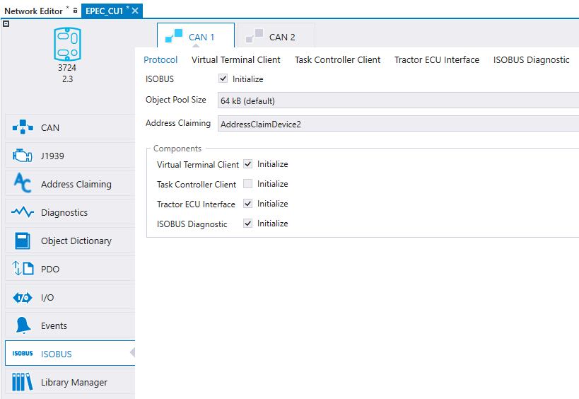
To initialize ISOBUS functionalities:
Double-click the correct device to open the device configuration
Select ISOBUS tab and the correct CAN channel
Select ISOBUS Initialize
Select a value for Object Pool Size. The downloaded binary file needs to fit into the reserved space. Note that for 3000-series control units, the setting will decrease the space available for CODESYS application (768 kB total size or 1088kB total size for EM units.).
Select the correct Address Claiming device for ISOBUS. If the Address Claiming dropdown list does not contain any items go to the Address Claiming tab to add a new Address Claiming.
Select Initialize for the wanted ISOBUS functionalities
The address claiming configuration can be done in Address Claiming tab.
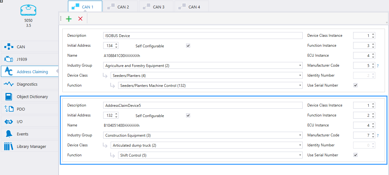
1. Define Initial Address for the device (value 0 - 253). Some of the addresses are reserved for certain device types (defined in standard ISO 11783-1).
It is recommended to use values 128 - 237 for implement application.
2. Define a name for the device that describes the device's functionality. Name for address claiming is combined from following fields. Definitions can be found from standard ISO 11783-5.
|
Field |
Description |
|
Description |
Description text of address claiming device. |
|
Self-configurable address |
Indicates if device can change it's initial address or not. Use always value 1 with ISOBUS devices |
|
Industry group |
Industry group, for example 2 = Agriculture and forestry equipment |
|
Device class |
Provides name for group of functions which are combined under same device class. For example 4 = planter and seeders |
|
Function |
Function for control function, for example 132 = Planters/Seeders Machine Control |
|
Device class instance |
Value is used to make difference for identical device classes in same network. 0 recommended. |
|
Function instance |
Value is used to make difference with several identical function instances. 0 recommended. |
|
ECU instance |
Value is used to make difference if there is several ECUs which together form a single function. 0 recommended (function is managed by one ECU). |
|
Manufacturer code |
Indicates the machine manufacturer (see www.sae.org for SAE Manufacturer Code Request). See also ISOBUS Data Dictionary http://dictionary.isobus.net/isobus/ > ISO 11783-1 Parameter group assignments: Complete list with details – PDF. |
|
Identity number |
Assigned by application code. It is recommended to use serial number for this field (select Use Serial Number box). |
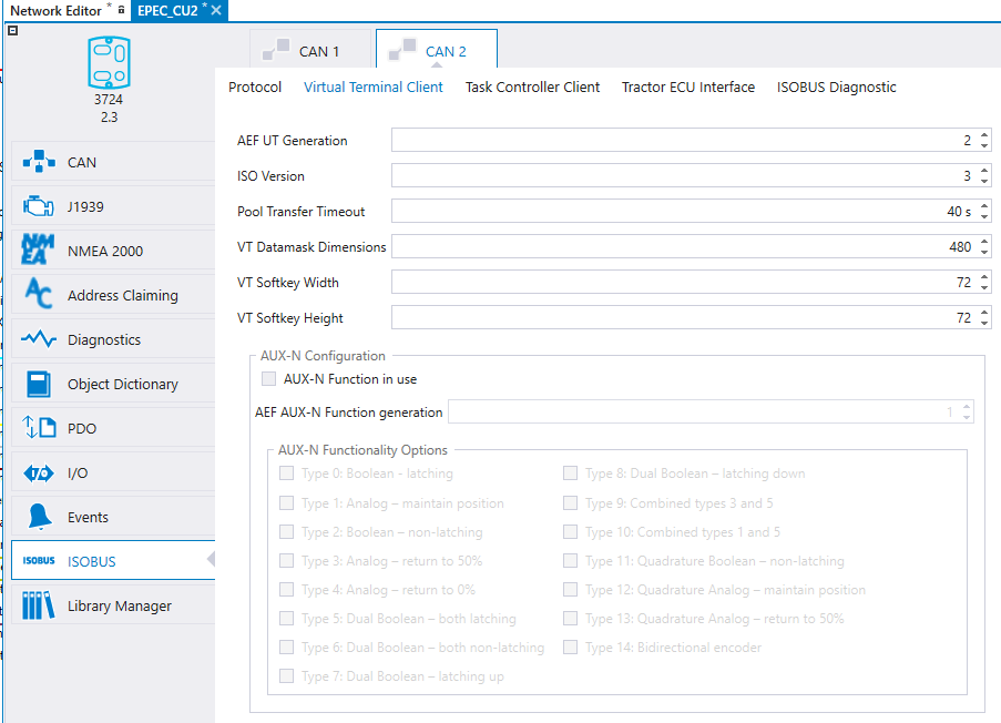
The selected ISOBUS functionalities have additional settings which are configured in ISOBUS tab.
|
|
The default dimensions for VT client data masks and soft keys are used in CODESYS code template and ISO-Designer template project. Changing the data mask or soft key dimensions in MultiTool Creator updates them into the CODESYS code template when MultiTool Creator System Export and CODESYS macro Edit > Import MultiTool is run. Dimension update should be manually changed into the ISO-Designer project (Hardware > Properties).
|
|
|
AUX-N Function is initialized from ISOBUS > Virtual Terminal Client tab. AUX-N requires VT client functionality.
|
The following tables describe the ISOBUS Components' settings and their default values.
|
Configuration |
Default Value |
Range |
Description |
|
AEF UT Generation |
2 |
1 - 2 |
UT functionality generation which application is designed for. Generations are defined by AEF. Used in Diagnostics Functionalities PGN message. Note that the UT generation and VT ISO Version are related (UT1.0 = VT V2, UT2.0 = VT V3). |
|
ISO Version |
3 |
2 - 4 |
ISO 11783-6 defines the VT versions. The value indicates the version which VT object pool is designed for and is used to configure VT client. Note that Jetter ISO-Designer™ project should use the same version. |
|
Timeout for Pool Transfer |
40 seconds |
20 - 150 |
VT client's object pool transfer sequence timeout. Increase the value if large VT object pool is used. |
|
VT Datamask Dimensions |
480 |
200 - 1000 |
Datamask resolution (width&height) which application is designed for. Should match with Jetter ISO-Designer™ project's datamask size. The value is used for VT client's scaling operations. |
|
VT Softkey Width |
72 |
60 - 200 |
Softkey width which application is designed for. Should match with Jetter ISO-Designer™ project's softkey width. The value is used for VT client's scaling operations. |
|
VT Softkey Height |
72 |
32 - 200 |
Softkey height which application is designed for. Should match with Jetter ISO-Designer™ project's softkey height. The value is used for VT client's scaling operations. |
Following VT client settings are AUX-N Function related
|
Configuration |
Default Value |
Range |
Description |
|
AUX-N Function in use |
FALSE |
FALSE/TRUE |
AUX-N function is taken in use when setting is TRUE. Requires VT client version 3 or higher. |
|
AEF AUX-N Function generation |
1 |
1 |
AUX-N functionality generation which application is designed for. Generations are defined by AEF. Used in Diagnostics Functionalities PGN message. |
|
AUX-N Functionality options |
FALSE |
FALSE/TRUE |
AUX-N Function types 0...14 each has ON/OFF setting which is used in Diagnostic Functionalities PGN message. Those AUX-N Function types which are used by application shall be checked TRUE. |
|
Configuration |
Default Value |
Range |
Description |
|
AEF TC Generation |
1 |
1 |
TC functionality generation which application is designed for. Generations are defined by AEF. Used in Diagnostics Functionalities PGN message. Note that the TC generation and ISO Version are related (TC1.0 = TC V3). |
|
ISO Version |
3 |
3 |
ISO 11783-10 defines TC versions. The value indicates version which TC object pool is designed for and used to configure TC client. |
|
Timeout for Pool Transfer |
20 seconds |
10 - 60 |
TC client's object pool transfer sequence timeout. The value should be increased if large TC object pool is used. |
|
TC-BAS Configuration |
|||
|
TC-BAS Selected |
FALSE |
FALSE/TRUE |
Set TRUE if application implements TC-BAS functionality (see ISO 11783-10:2015 Annex F for more info). Enables TC-BAS in Diagnostics Functionalities PGN message. |
|
TC-GEO Configuration |
|||
|
TC-GEO Selected |
FALSE |
FALSE/TRUE |
Set TRUE if application implements TC-GEO functionality (see ISO 11783-10:2015 Annex F for more info). Enables TC-GEO in Diagnostics Functionalities PGN-message. |
|
Number of Control Channels |
1 |
1 - 255 |
Defines how many control channels are required by application. The value configures TC client and Diagnostics Functionalities PGN message. |
|
Polygon Based Prescription Maps Supported |
FALSE |
FALSE/TRUE |
Defines if application supports the TC-GEO option. If Enabled, the option is set to Diagnostics Functionalities PGN message. |
|
TC-SC Configuration |
|||
|
TC-SC Selected |
FALSE |
FALSE/TRUE |
Set TRUE if application implements TC-SC functionality (see ISO 11783-10:2015 Annex F for more info). Enables TC-SC in Diagnostics Functionalities PGN message. |
|
Number of Booms |
1 |
1 - 255 |
Defines how many booms are required by application. The value configures TC client and Diagnostics Functionalities PGN message. |
|
Number of Sections |
1 |
1 - 255 |
Defines how many sections are required by application. The value configures TC client and Diagnostics Functionalities PGN-message. |
|
Configuration |
Default Value |
Range |
Description |
|
AEF TECU Generation |
1 |
1 |
TECU functionality generation which application is designed for. Generations are defined by AEF. Used in Diagnostics Functionalities PGN message. |
|
TECU Class |
2 |
1 - 3 |
TECU class which is required by application. Selected class affects which signals are requested from TECU and also Diagnostics Functionalities PGN message. |
Settings in ISOBUS Diagnostics tab configure the contents of Diagnostics PGN messages.
Note that some information from VT, TC and TECU tabs are also used for Diagnostics Functionalities message.
|
Configuration |
Default Value |
Range |
Description |
|
AEF Min CF Generation |
1 |
1 |
Minimum Control Function functionality generation which application is designed for. Generations are defined by AEF. Used in Diagnostics Functionalities PGN message. |
|
Software Identification |
|||
|
ECU FW Version |
From system parameters |
N/A |
FW version is automatically read from the control unit's system parameters to the Software Identification PGN. |
|
Application SW Version |
Empty string |
ASCII (80 char) |
Application specific version info to Software Identification PGN. |
|
ECU Identification Info |
|||
|
ECU Part Number |
Empty string |
ASCII (20 char) |
ECU part number to ECU Identification Info PGN (e.g. unit's E-code). |
|
ECU Serial Number |
From system parameters |
N/A |
Serial number is automatically read from the control unit's system parameters to the ECU Identification Info PGN. |
|
ECU Location |
Empty string |
ASCII (20 char) |
Location of the ECU in implement to the ECU Identification Info PGN. |
|
ECU Type |
From system parameters |
N/A |
Control unit type is automatically read from the control unit's system parameters to the ECU Identification Info PGN. |
|
ECU Manufacturer |
Epec Oy |
ASCII (20 char) |
Manufacturer name to the ECU Identification Info PGN. |
|
ECU Hardware ID |
Hardware specific identifier in AEF database |
ASCII (80 char) |
ECU hardware identifier to the ECU Identification Info PGN. MultiTool 5.9 and newer or MultiTool Creator initializes this field with control unit specific AEF database identifier. |
|
ISOBUS Compliance Certification |
|||
|
Protocol Year |
Current year |
2000 - 2061 |
Defined by test laboratory for conformance test. |
|
Protocol Revision |
1 |
0 - 30 |
Defined by test laboratory for conformance test. |
|
Laboratory ID |
0 |
0 - 2047 |
Defined by test laboratory for conformance test. For non-certified setting, an own manufacturer code can be used. |
|
Laboratory Type |
Self-certification (non-certified laboratory) |
Self-certification, AEF Certified, Reserved, N/A (Not Certified) |
Defined by test laboratory for conformance test. |
|
Reference Number |
0 |
0 - 65535 |
Defined by test laboratory for conformance test. |
|
Product Identification Info |
|||
|
Code |
Empty string |
ASCII (50 char) |
End product's identification code. |
|
Brand |
Empty string |
ASCII (50 char) |
End product's brand name. |
|
Model |
Empty string |
ASCII (50 char) |
End product's model name. |
To create CODESYS project, select the device in MultiTool Creator and press  icon.
icon.
MultiTool Creator creates a device folder including:
CODESYS project file (.pro)
Libraries folder
ISOBUS folder including
Jetter folder
Empty ISO-Designer project template with one Working Set and Data Mask
Python folder
Converters to handle changes between ISO-Designers and CODESYS
BinaryMaker folder includes the object pool download.bin (combined from folder Exp)
|
|
For AUX-N implementation guide, see How to use AUX Functions.
It is recommended to have knowledge on how to build basic ISOBUS VT project before adding AUX-N Functions. |
Building CODESYS project for ISOBUS VTBuilding CODESYS project for ISOBUS VT
ISOBUS VT pool is created using the Jetter ISO-designer™. MultiTool Creator adds the needed initializations for the device.
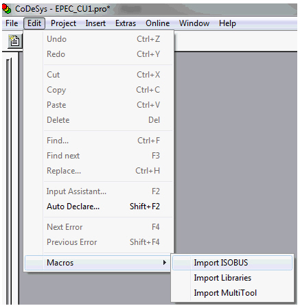
To add ISOBUS code template to the CODESYS project, run Edit > Macros > Import ISOBUS. Running the macro
adds ISOBUS programs, object handlers and a template program for data/alarm masks
updates object pool (downloaded binary)
updates code template’s list of object pool’s objects (global variables > ISOBUS VT > ISOBUS_CANx > IsobusExportVtInfo)
When importing ISOBUS files, CODESYS requests to overwrite objects. Answer Yes to these pop-ups.
The VT client program ISOBUS_CANx_IsobusVt requires own programs for user initialization and update code. These programs are called in ISOBUS_CANx_IsobusVt (PRG) actions actInit and actUpdate.
Add two programs (ST language recommended) with the following names (x according to the CAN interface)
ISOBUS_CANx_IsobusVtInitUserCode (PRG)
ISOBUS_CANx_IsobusVtUpdateUserCode (PRG)
ISOBUS_CANx_IsobusVtInitUserCode (PRG) is used, for example, to initialize ISO-designer elements such as buttons and numeric input/output fields.
ISOBUS_CANx_IsobusVtUpdateUserCode (PRG) is called each program cycle after VT client is updated.
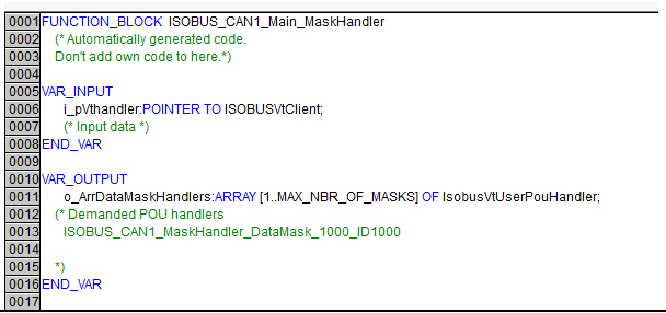
The template ISO-Designer project for VT client includes one working set and one data mask (named as DataMask_1000). Each VT data/alarm mask requires its own handler program into CODESYS project which is called when the mask is active.
Data/Alarm mask handler program are required to have predefined inputs and outputs. Import ISOBUS macro generates names for each mask to ISOBUS_CANx_Main_MaskHandler declaration part as a comment.
The easiest way to make a handler program is to
1. copy-paste a template program called TEMPLATE_HANDLER (PRG)
2. copy data mask handler name from ISOBUS_CANx_Main_MaskHandler program comment: ISOBUS_CANx_MaskHandler_DataMask_1000_ID1000
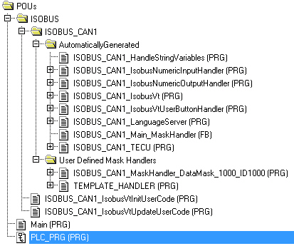
A complete project looks like this:
The project is now ready to be build. Build the CODESYS project but don't download it to the unit yet.
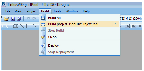
Object pool is edited with 3rd party program Jetter ISO-designer™. MultiTool adds a template ISOBUS pool project for ISO-designer™ to {DeviceFolder}\ISOBUS\Jetter\IsobusVtObjectPool.jvw.
Open this project file by double-clicking it (Jetter ISO-designer™ should be installed). To build the ISO-Designer template project, select Build > Build project 'IsobusVtObjectPool'.
|
|
Run Import ISOBUS macro described below every time you have made changes to Jetter ISO-designer™ project or to the language XML. |
In CODESYS 2.3 device project, run Edit > Macros > Import ISOBUS
When importing ISOBUS files, CODESYS requests to overwrite objects. Answer Yes to these pop-ups.
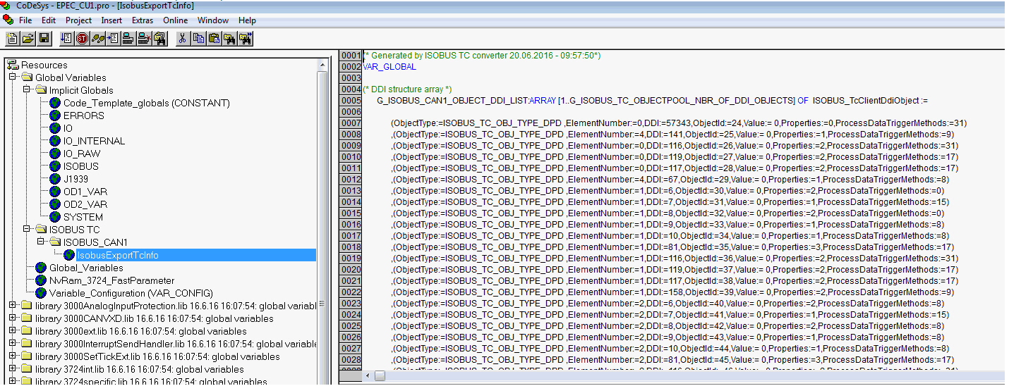
Check from Globals, that the updated exp file is imported:
ISOBUS import macro creates also a binary file which is downloaded to the unit. This binary contains ISOBUS related data, for example, object pool. The binary file is downloaded with CANmoon. Open CANmoon and select Configuration > Actions > Download > Software.
|
|
Note that CANopen is recommended to be initialized to find the unit with CANmoon scan.
|
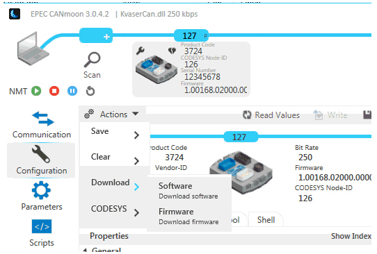
Select object pool binary file {DeviceFolder}\ISOBUS\python\BinaryMaker\Downloaded.bin and download it to the unit.
Download CODESYS application normally to the device and reboot the device:
1. Check the control unit communication parameters
- By default, the units have CODESYS communication node-ID 126 (download node-ID), Application node-ID 127
2. Define the communication parameters to CODESYS Online > Communication Parameters...
3. Login and download with CODESYS Online > Login
4. Power cycle the control unit each time after dowloading CODESYS application and object pool.
Connect VT to the same CAN bus with the unit (VT can be connected all times to the bus when updating application or object pool). When VT is started, the device downloads the pool to VT and starts to use it.
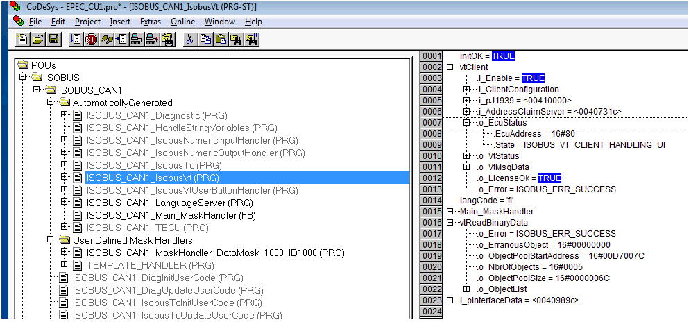
Go online with CODESYS 2.3 and check the following issues.
Open Program ISOBUS_CAN1_IsobusVt and open POU as shown in image below.
| Variable | Description | Reason to error | Resolution |
|
vtClient::o_LicenseOk |
Flag value must be TRUE. This flag tells if device has ISOBUS license activated. |
Unit ISOBUS license is not activated. |
Please contact Epec to order a unit with ISOBUS license activated. |
|
vtClient::o_EcuStatus::State |
Value ISOBUS_VT_CLIENT_HANDLING_UI tells that vtClient is downloaded pool successfully to unit and it can be used. |
Any other state informs error for example in address claiming or pool download. |
No exact resolution for this error. |
|
vtReadBinaryData::o_Error |
Value ISOBUS_ERR_SUCCESS tells that vtClient has read pool binary successfully from device flash. |
For some reason pool read from flash is failed. |
Try to download pool again with CANmoon. |
11. Continue with training project from Epec Extranet to use ISO-Designer elements and make functionalities into CODESYS application.
Building CODESYS project for ISOBUS TC Building CODESYS project for ISOBUS TC
Add the following programs to the project. ISOBUS_CAN{X}_IsobusVtInitUserCode is used, for example, to initialize ISO-designer elements such as buttons and input fields. Every data mask requires it's own handler program.
|
Name |
Type |
Related option |
Description |
|
ISOBUS_CAN{X}_IsobusTcInitUserCode |
PRG |
TC client |
Called after ISOBUS TC client is initialized. {X} is used CAN interface. |
|
ISOBUS_CAN{X}_IsobusTcUpdateUserCode |
PRG |
TC client |
Called after ISOBUS TC client is updated. {X} is used CAN interface. |
|
|
Run Import ISOBUS macro described below every time you have made changes to Jetter ISO-designer™ project, or to the language xml. |
In CODESYS 2.3 device project, run Edit > Macros > Import ISOBUS
When importing ISOBUS files, CODESYS requests to overwrite objects. Answer Yes to these pop-ups.
Check from Globals, that the updated exp file is imported:
The project is now ready to be build. Build the CODESYS project but don't download it to the unit yet.
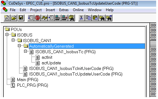
Project looks something like this.
ISOBUS import macro creates also a binary file which is downloaded to the unit. This binary contains ISOBUS related data, for example object pool. Binary file is downloaded with CANmoon. Open CANmoon and select Configuration > Actions > Download > Software.
Note that CANopen must be initialized to use CANmoon.
Select binary file {DeviceFolder}\ISOBUS\python\BinaryMaker\Downloaded.bin and download it to the unit.
Download CODESYS application normally to the device and reboot the device.
Connect TC to the same CAN bus with the unit (TC can be connected all times to the bus when updating application or object pool). When TC is started, the device downloads the pool to TC and starts to use it.
It is possible to set different values in TC object pool. These values are set online when pool is downloaded. Code examples for these settings:
Implement serial number:
ISOBUS_CAN1_IsobusTc.i_ClientSerialNumber := '1234567';
Implement TC client pool serial number:
ISOBUS_CAN1_IsobusTc.i_ClientSwVersion := 'My sw version is 1234.45567';
Default value for DPT:
G_ISOBUS_CAN1_OBJECT_DDI_LIST[G_ISOBUS_CAN1_DDI_ID_DPT_Seed_drill_body_Maximum_working_width_70].Value:= 4000;
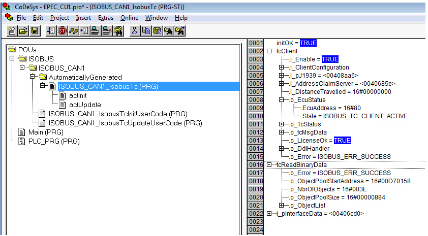
Go online with CODESYS 2.3 and check the following issues.
Open Program ISOBUS_CAN1_IsobusTc and open POU as shown in image below.
| Variable | Description | Reason to error | Resolution |
| vtClient::o_LicenseOk | Flag value must be TRUE. This flag tells if device has ISOBUS license activated. | Unit ISOBUS license is not activated. | Please contact to Epec to order a unit with ISOBUS license activated. |
| tcClient::o_EcuStatus::State | Value ISOBUS_TC_CLIENT_ACTIVE tells that tcClient is downloaded pool successfully to unit and it can be used. | Any other state informs error for example in address claiming or pool download. | No exact resolution for this error. |
| tcReadBinaryData::o_Error | Value ISOBUS_ERR_SUCCESS tells that tcClient has read pool binary successfully from device flash. | For some reason pool read from flash is failed. | Try to download pool again with CANmoon. |
Building CODESYS project for ISOBUS Tractor-ECUBuilding CODESYS project for ISOBUS Tractor-ECU
In CODESYS 2.3 device project, run Edit > Macros > Import ISOBUS
When importing ISOBUS files, CODESYS requests to overwrite objects. Answer Yes to these pop-ups.
Add the following programs to the project. User programs can be used for application specific code.
|
Name |
Type |
Description |
|
ISOBUS_CAN{X}_TecuInitUserCode |
PRG |
Called after ISOBUS TECU is initialized. {X} is used CAN interface. |
|
ISOBUS_CAN{X}_TecuUpdateUserCode |
PRG |
Called after ISOBUS TECU is updated. {X} is used CAN interface. |
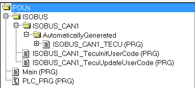
Complete project looks like below.
Note that ISOBUS folder may have other programs too if you have more than one ISOBUS component initialized.
Download CODESYS application normally to the device and reboot the device.
Connect TECU to the same CAN bus with the unit (TECU can be connected all times to the bus when updating application). When TECU and device are connected to the same bus, PGN messages will be received.
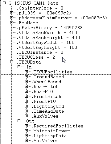
TECU message data can be accessed by application through Codesys Resources tab > ISOBUS variable list > G_ISOBUS_CAN{X}_Data.TECUData (see image below).
For code use case examples see ISOBUS_ImplementTECUFacilities (FB) topic in ISOBUS library's software manual (Epec Programming and Libraries manual, available in Epec Extranet).
Go online with CODESYS 2.3 and check the following issues.
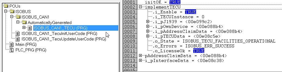
Open Program ISOBUS_CAN1_TECU and open POU as shown in image below.
| Variable | Description | Reason to error | Resolution |
|
implementTECU::o_LicenseOk |
Flag value must be TRUE. This flag tells if device has ISOBUS license activated. |
Unit ISOBUS license is not activated. |
Please contact to Epec to order a unit with ISOBUS license activated. |
|
implementTECU::o_Errors |
Value depends on error. ISOBUS_ERR_SUCCESS tells that there is no errors. |
Message initialization could have failed or license is missing. |
Please contact Epec with specific error code. |
Building CODESYS project for ISOBUS DiagnosticBuilding CODESYS project for ISOBUS Diagnostic
In CODESYS 2.3 device project, run Edit > Macros > Import ISOBUS
When importing ISOBUS files, CODESYS requests to overwrite objects. Answer Yes to these pop-ups.
Add the following programs to the project. User programs can be used for application specific code.
|
Name |
Type |
Description |
|
ISOBUS_CAN{X}_DiagInitUserCode |
PRG |
Called before ISOBUS diagnostic is initialized. {X} is used CAN interface. |
|
ISOBUS_CAN{X}_DiagUpdateUserCode |
PRG |
Called after ISOBUS diagnostic is updated. {X} is used CAN interface. |
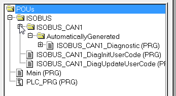
Complete project looks like below.
Note that ISOBUS folder may have other programs too if you have more than one ISOBUS component initialized.
MultiTool Creator does not currently support ISOBUS diagnostic PGN configuration but it can be done in Codesys.
Diagnostic message configurations can be accessed by application through Codesys Resources tab > ISOBUS variable list > G_ISOBUS_CAN{X}_Data.DiagConfig (see image below).
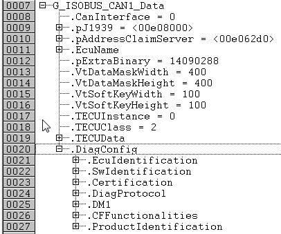
Below is an example of initialization code which can be added to ISOBUS_CAN1_DiagInitUserCode PRG. The messages are defined in ISO 11783-12 standard.
CFF message's Enabled flags state depend on which ISOBUS components are used by application.
Diagnostic messages are sent to bus only on request by other devices (except DM1 log).
For DM1 use case example, see ISOBUS_SPNFMI_ToDTC (FUN) topic in ISOBUS library's software manual (Epec Programming and Libraries Manual, available in Epec Extranet).
(*Configure ICC PGN*)
G_ISOBUS_CAN1_Data.DiagConfig.Certification.TestProtocolYear := 2016;
G_ISOBUS_CAN1_Data.DiagConfig.Certification.TestProtocolRevision := 2;
G_ISOBUS_CAN1_Data.DiagConfig.Certification.LaboratoryID := 0;
G_ISOBUS_CAN1_Data.DiagConfig.Certification.LaboratoryType := ISOBUS_LAB_TYPE_SELF;
G_ISOBUS_CAN1_Data.DiagConfig.Certification.ReferenceNumber := 20000;
(*Configure ECUID PGN*)
G_ISOBUS_CAN1_Data.DiagConfig.EcuIdentification.ECU_PartNumber := 'E30E3606-23';
G_ISOBUS_CAN1_Data.DiagConfig.EcuIdentification.ECU_SerialNumber := DWORD_TO_STRING(SYSTEM_SerialNumber);
G_ISOBUS_CAN1_Data.DiagConfig.EcuIdentification.ECU_Location := 'Implement';
G_ISOBUS_CAN1_Data.DiagConfig.EcuIdentification.ECU_Type := DWORD_TO_STRING(SYSTEM_ControlUnitType);
G_ISOBUS_CAN1_Data.DiagConfig.EcuIdentification.ECU_Manufacturer := 'Epec Oy';
G_ISOBUS_CAN1_Data.DiagConfig.EcuIdentification.ECU_HardwareID := '000215';
(*Configure SOFT PGN*)
G_ISOBUS_CAN1_Data.DiagConfig.SwIdentification.ECU_FW := SYSTEM_FW_VERSION;
G_ISOBUS_CAN1_Data.DiagConfig.SwIdentification.Application_SW := 'App sw 1.23.4';
(*Configure DIAG PGN*)
G_ISOBUS_CAN1_Data.DiagConfig.DiagProtocol.Protocols[1] := ISOBUS_DIAG_ISO_11783;
(*Configure PII PGN*)
G_ISOBUS_CAN1_Data.DiagConfig.ProductIdentification.PI_Code := '123456789';
G_ISOBUS_CAN1_Data.DiagConfig.ProductIdentification.PI_Brand := 'DemoBrand';
G_ISOBUS_CAN1_Data.DiagConfig.ProductIdentification.PI_Model := 'Model ABC';
(*Configure CFF PGN*)
G_ISOBUS_CAN1_Data.DiagConfig.CFFunctionalities.CFF_MinCF.Enabled := TRUE;
G_ISOBUS_CAN1_Data.DiagConfig.CFFunctionalities.CFF_MinCF.Generation := 1;
G_ISOBUS_CAN1_Data.DiagConfig.CFFunctionalities.CFF_MinCF.Options[1] := ISOBUS_CFF_OPT_MINCF_NONE;
G_ISOBUS_CAN1_Data.DiagConfig.CFFunctionalities.CFF_TECUBasicClient.Enabled := TRUE;
G_ISOBUS_CAN1_Data.DiagConfig.CFFunctionalities.CFF_TECUBasicClient.Generation := 1;
G_ISOBUS_CAN1_Data.DiagConfig.CFFunctionalities.CFF_TECUBasicClient.Options[1] := ISOBUS_CFF_OPT_TECU_BAS_CLASS2;
G_ISOBUS_CAN1_Data.DiagConfig.CFFunctionalities.CFF_TECUBasicClient.Options[2] := ISOBUS_CFF_OPT_TECU_BAS_F;
G_ISOBUS_CAN1_Data.DiagConfig.CFFunctionalities.CFF_TECUBasicClient.Options[3] := ISOBUS_CFF_OPT_TECU_BAS_L;
G_ISOBUS_CAN1_Data.DiagConfig.CFFunctionalities.CFF_UTClient.Enabled := TRUE;
G_ISOBUS_CAN1_Data.DiagConfig.CFFunctionalities.CFF_UTClient.Generation := 2;
G_ISOBUS_CAN1_Data.DiagConfig.CFFunctionalities.CFF_UTClient.Options[1] := ISOBUS_CFF_OPT_UT_NONE;
G_ISOBUS_CAN1_Data.DiagConfig.CFFunctionalities.CFF_TCBasicClient.Enabled := TRUE;
G_ISOBUS_CAN1_Data.DiagConfig.CFFunctionalities.CFF_TCBasicClient.Generation := 1;
G_ISOBUS_CAN1_Data.DiagConfig.CFFunctionalities.CFF_TCBasicClient.Options[1] := ISOBUS_CFF_OPT_TC_BAS_NONE;
G_ISOBUS_CAN1_Data.DiagConfig.CFFunctionalities.CFF_TCSectionClient.Enabled := TRUE;
G_ISOBUS_CAN1_Data.DiagConfig.CFFunctionalities.CFF_TCSectionClient.Generation := 1;
G_ISOBUS_CAN1_Data.DiagConfig.CFFunctionalities.CFF_TCSectionClient.NumOfBooms := 1;
G_ISOBUS_CAN1_Data.DiagConfig.CFFunctionalities.CFF_TCSectionClient.NumOfSections := 2;
G_ISOBUS_CAN1_Data.DiagConfig.CFFunctionalities.CFF_TCGeoClient.Enabled := FALSE;
G_ISOBUS_CAN1_Data.DiagConfig.CFFunctionalities.CFF_TCGeoClient.Generation := 1;
G_ISOBUS_CAN1_Data.DiagConfig.CFFunctionalities.CFF_TCGeoClient.SupportedChannels := 1;
G_ISOBUS_CAN1_Data.DiagConfig.CFFunctionalities.CFF_TCGeoClient.Options[1] := ISOBUS_CFF_OPT_TC_GEO_NONE;
Download CODESYS application normally to the device and reboot the device.
Go online with CODESYS 2.3 and check the following issues.
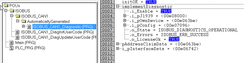
Open Program ISOBUS_CAN1_Diagnostic and open POU as shown in image below.
| Variable | Description | Reason to error | Resolution |
|
implementDiagnostic::o_LicenseOk |
Flag value must be TRUE. This flag tells if device has ISOBUS license activated. |
Unit ISOBUS license is not activated. |
Please contact Epec to order a unit with ISOBUS license activated. |
|
implementDiagnostic::o_Errors |
Value depends on error. ISOBUS_ERR_SUCCESS tells that there is no errors. |
Message initialization could have failed or license is missing. |
Please contact Epec with specific error code. |
See also,
Epec MultiTool Creator Manual (available in Epec Extranet)
Training material (available in Epec Extranet)
Source file topic100343.htm
Last updated 4-Sep-2025