Supported
platforms: CODESYS 2.3, CODESYS 3.5
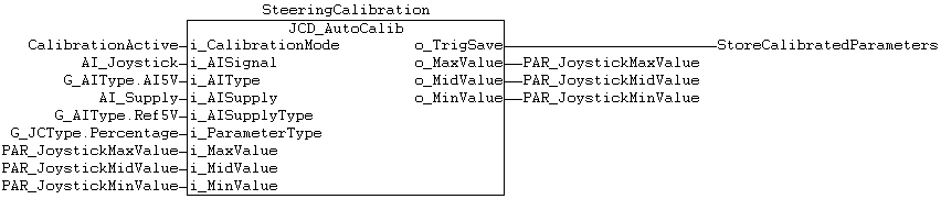
JCD_AutoCalib (FB)
Description
JCD_AutoCalib function block can be used for calibration of the joystick
or pedal.
In the calibration mode, it measures the value of i_AISignal,
converts it to the voltage value with the ADC_To_mAOrV
function, and stores the maximum and minimum values of the measured signal
(meanwhile the user moves the joystick or pedal to both end positions).
Mid position value of the joystick is stored when the calibration mode
is deactivated. The joystick should be centered when the calibration mode
is deactivated.
o_TrigSave output is activated
for one program cycle, when the calibration mode is deactivated (at falling
edge). This output can be used to trigger an additional parameter saving
function if necessary (for example if parameters are stored to FLASH memory).
Current calibration parameter values are given to the FB as inputs and
the FB's output calibration values are assigned to those same variables.
When the calibration mode is not active, input calibration values are
directly assigned to output calibration values, therefore calibration
values only change during calibration mode.
With G_JCType.Percentage type given to i_ParameterType,
max, mid and min calibration values are percentage (1000 = 100,0%) of
measured
joystick supply voltage.
The calibration type changes internally only on rising edge of
i_CalibrationMode.
Limitations

|
Calibration has 2 operation modes:
- Voltage mode: Input parameters are given in volts
and joystick supply voltage is not compensated.
- Percentage mode: Input parameters are given in
percentage of joystick supply voltage. Due to that, changes in
joystick supply voltage are compensated. |

|
In voltage mode ( i_ParameterType
= G_JCType.Voltage),
both output and input calibration parameters are handled as volts
(1000 = 10,00V).
In percentage mode ( i_ParameterType
= G_JCType.Percentage),
both output and input calibration parameters are handled as proportion
(1000 = 100,0%) of joystick supply voltage. |
|
Joystick and pedal must be connected to voltage
input. |
|
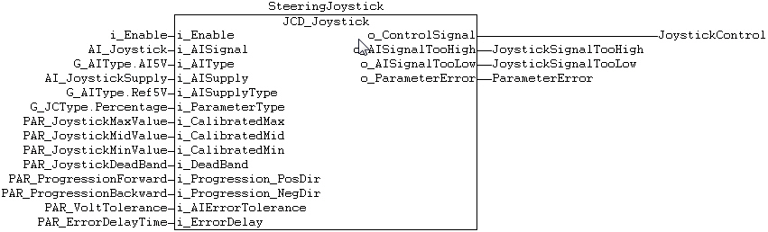
When
i_ParameterType =
G_JCType.Voltage and
voltage values are used for joystick calibration, there is a reference
voltage monitoring feature built in to detect drop of reference
voltage level. In such case, o_Control signal output is
reset and can be used again after rising edge of i_Enable.
This monitoring feature can however detect only sudden drop of
ref voltage level. |
|
It is highly
recommended to set i_ParameterType
to
G_JCType.Percentage and
to use percentage values for joystick calibration. This ensures
that unexpected dropping of reference voltage level doesn’t cause
o_ControlSignal output changing and unwanted response in
controlled actuator. |
Inputs
CODESYS 2.3CODESYS 2.3
Input
variable name |
Data
type |
Range |
Description |
i_CalibrationMode |
BOOL |
FALSE/TRUE |
AI signal is monitored and calibration
is done when value is true |
i_AISignal |
UINT |
Hardware specific |
Analog input signal |
i_AIType |
BYTE |
0..G_ADScaleArrMax |
Defines the Analog input type
and range |
i_AISupply |
UINT |
Hardware specific |
Joystick supply voltage measurement |
i_AISupplyType |
BYTE |
0..G_ADScaleArrMax |
Joystick supply type and range. |
i_ParameterType |
ENUM |
G_JCType.Voltage, G_JCType.Percentage |
Calibration parameter type Voltage/Percentage |
i_MaxValue |
UINT |
Hardware and calibration type
specific |
Maximum calibration value of joystick
or pedal. Value is given in voltage (500 = 5,00V) or percentage
(1000 = 100,0%). |
i_MidValue |
UINT |
Hardware and calibration type
specific |
Middle calibration value of joystick
or minimum value of pedal. Value is given in voltage (500
= 5,00V) or percentage (1000 = 100,0%). |
i_MinValue |
UINT |
Hardware and calibration type
specific |
Minimum calibration value of joystick
or pedal. Value is given in voltage (500 = 5,00V) or percentage
(1000 = 100,0%). |
CODESYS 3.5CODESYS 3.5
Input
variable name |
Data
type |
Range |
Description |
i_CalibrationMode |
BOOL |
FALSE/TRUE |
AI signal is monitored and calibration
is done when value is true |
i_AISignal |
UINT |
Hardware specific |
Analog input signal |
i_AIType |
ADData |
G_AIType struct
|
Defines the Analog input type
and range |
i_AISupply |
UINT |
Hardware specific |
Joystick supply voltage measurement |
i_AISupplyType |
ADData |
G_AIType struct |
Joystick supply type and range. |
i_ParameterType |
ENUM |
G_JCType.Voltage, G_JCType.Percentage |
Calibration parameter type Voltage/Percentage |
i_MaxValue |
UINT |
Hardware and calibration type
specific |
Maximum calibration value of joystick
or pedal. Value is given in voltage (500 = 5,00V) or percentage
(1000 = 100,0%). |
i_MidValue |
UINT |
Hardware and calibration type
specific |
Middle calibration value of joystick
or minimum value of pedal. Value is given in voltage (500
= 5,00V) or percentage (1000 = 100,0%). |
i_MinValue |
UINT |
Hardware and calibration type
specific |
Minimum calibration value of joystick
or pedal. Value is given in voltage (500 = 5,00V) or percentage
(1000 = 100,0%). |
Outputs
Output variable
name |
Data type |
Range |
Description |
o_TrigSave |
BOOL |
FALSE/TRUE |
True for one cycle after calibration
end, can be used trigger parameter saving |
o_MaxValue |
UINT |
Hardware and calibration type specific |
Maximum calibration value of joystick
or pedal. Value is given in voltage (500 = 5,00V) or percentage
(1000 = 100,0%). |
o_MidValue |
UINT |
Hardware and calibration type specific |
Middle calibration value of joystick
or minimum value of pedal. Value is given in voltage (500 = 5,00V)
or percentage (1000 = 100,0%). |
o_MinValue |
UINT |
Hardware and calibration type specific |
Minimum calibration value of joystick
or pedal. Value is given in voltage (500 = 5,00V) or percentage
(1000 = 100,0%). |
Example code

NOTE! Example's StoreJoystickCalibrationToFlash is not implemented in
the library.
See also
ADC_To_mAorV (FUN)
Source file Topic000369.htm
Last updated 4-Sep-2025